
Stay updated with the latest company news, product innovations, exhibition highlights, and industry trends. Explore valuable insights into pressure vessel technologies and global markets.
Particulate: maximum ≤ 50 µm; next‑generation platforms tightening to ≤ 25 µm
Chloride: As low as practicable — commonly < 50 mg/L in liquid cooling loop specifications
Glycol concentration: 25 % ± tolerance, verified by refractometer
\(Water\ basis:\ Flow =120 /(1.163 × 10)=10.32\ m^{3}/h=172\ L/min\) \(Q\ (kW)=0.0698 × Flow\ (L/min) × \Delta T(K)\)
Redundancy: N+1 or N+N pumps within the CDU, hot‑swappable where possible; N+1 CDUs at row level; diversified sizing so a single failure removes a small fraction of capacity; dual power feeds; and buffer capacity on the facility side to bridge changeover intervals.
Control: PID holding secondary supply temperature within ±0.5 to ±1 °C, pump speed modulation to track load, secondary‑side pressurization above atmospheric, leak detection with staged alarm and shutdown, and communications via Modbus TCP, SNMP, BACnet and increasingly Redfish.
See How Does a CDU Work? for the full component‑level breakdown.
Secondary connections use OCP‑standardized universal quick disconnects — UQD (hand‑plug) and UQDB (blind‑mate) — with Stäubli and CPC among the principal suppliers. Stäubli's UQD is explicitly noted as approved by NVIDIA for these platforms.
Their role is essential to serviceability: a compute tray must be withdrawable from a live rack without draining the loop or interrupting cooling to the other trays. This requires dry‑break, low‑spill couplings with defined residual drip allowances and a maintenance procedure that respects them.
Specification points: coupling pressure rating and pressure drop at the actual flow rate, residual drip volume, insertion force, cycle life, material compatibility with PG25 and the inhibitor package, and elastomer grade. Quick disconnects are a common source of both flow restriction and leakage, and they are cheap relative to the downtime they cause.
A GB200 NVL72 rack weighs on the order of 1.36 tonnes. Standard raised‑floor data hall designs are frequently rated well below the point loads this creates. Floor loading assessment is a structural engineering exercise that must happen before the cooling design, because it determines whether the hall is usable at all — and adding a buffer tank, which weighs roughly a tonne per cubic metre when full, compounds it.
Non‑dielectric coolant inside a rack of live GPU hardware makes leak management a design discipline:
Leak detection — rope sensors along manifold routes, point sensors in CDU drip trays and under racks, integrated with the CDU controller and DCIM
Containment — drip trays, secondary containment under distribution routes, sealed penetrations
Staged response — alarm at first detection, controlled shutdown at second stage
Isolation — section valves allowing a rack or branch to be isolated without draining the hall
Maintenance procedures — for quick disconnect service, tray withdrawal and coolant sampling, with spill kits available at the point of work
Reference designs based on warm‑water (45 °C) loops with dry coolers approach near‑zero water consumption, because they eliminate evaporative rejection. Conventional cooling‑tower‑based designs consume substantially more — figures on the order of 2.6 million gallons per MW per year are cited for tower‑cooled plants. For AI facilities at tens or hundreds of megawatts, often in water‑stressed regions, this is a permitting and reputational issue as much as an operating cost.
The direction of travel is clear: warmer coolant classes reduce or eliminate mechanical refrigeration and evaporative water use. Designing a facility for W32 today when the next platform generation supports W45 is a stranded‑asset risk.
The CDU is a monitored, controlled device, not plumbing. It needs power (often dual feed), network connectivity to the DCIM, and integration into the alarm and shutdown hierarchy alongside the IT equipment. Specify the protocol your DCIM actually uses.
| Component | Function | Risk if omitted |
| Air / dirt separator | Removes entrained air and magnetite in‑line | Cavitation, noise, flow‑meter error, cold plate fouling, uneven flow distribution |
| Vacuum degasser | Removes dissolved oxygen to < 0.1 mg/L | Ongoing corrosion, magnetite generation, progressive efficiency loss |
| Filtration | Protects 200‑300 µm channels at 25 µm rating | Cold plate blockage, thermal excursion, rack derating |
| Material selection | 316L stainless against chloride pitting and SCC | Tank perforation, coolant loss on a live cluster |
Two of these deserve emphasis for GB200/GB300 specifically.
Air and gas management. With roughly 54 cold plates in parallel per rack and 200‑300 µm channels, a bubble lodged in one plate reduces local flow and raises local junction temperature. In a synchronized training job, the rack — and the job — runs at the speed of the hottest GPU. Gas management is a performance issue, not just a reliability issue.
Sizing on the actual coolant. PG25 expands roughly 1.3‑1.5× more than water over the same temperature rise, has roughly 5‑10 % lower volumetric heat capacity, and about 2× the viscosity. An expansion vessel sized on water properties is roughly 30 % undersized. A buffer tank sized on water properties under‑delivers ride‑through. Pump head calculated on water properties underestimates power. Every ancillary calculation must use the actual PG25 properties.
See How to Size an Expansion Vessel for Liquid Cooling and What Is a Buffer Tank in AI Data Center Cooling?
How much heat does a GB200 NVL72 rack produce?Around 120‑132 kW rated, with peaks reported at 130‑140 kW. Approximately 90 % or more is captured by liquid cooling at the cold plates; the remainder is rejected by residual air cooling within the rack.
Can I air‑cool GB200 NVL72?No. There is no air‑cooled variant. Liquid cooling is mandatory.
What is the difference between GB200 and GB300 for cooling purposes?GB300 NVL72 uses Blackwell Ultra GPUs at roughly 1,400 W each against around 1,000 W for B200, taking the rack to approximately 140 kW. That increases the required coolant flow and heat‑rejection capacity, assuming water chemistry is actively controlled.
See Liquid Cooling Reservoir Materials: 304 vs 316L Stainless Steel.
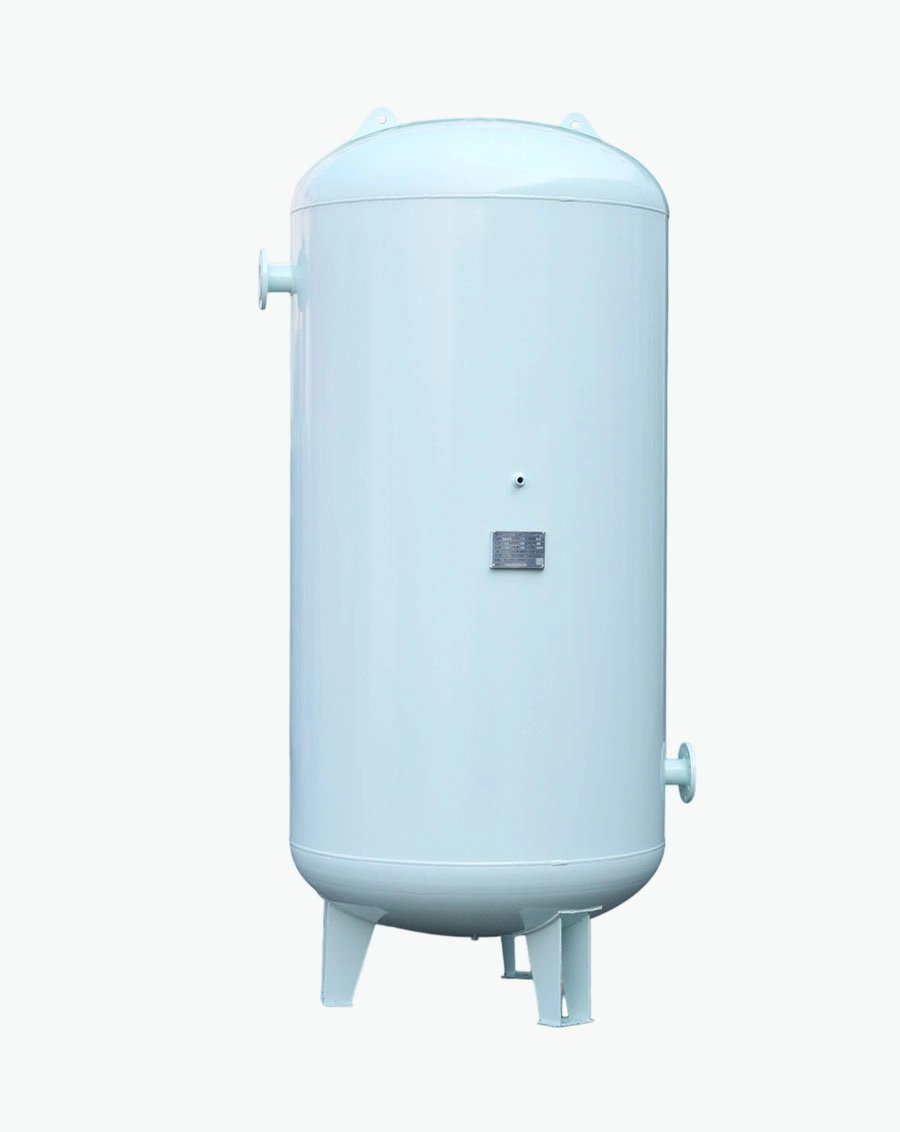
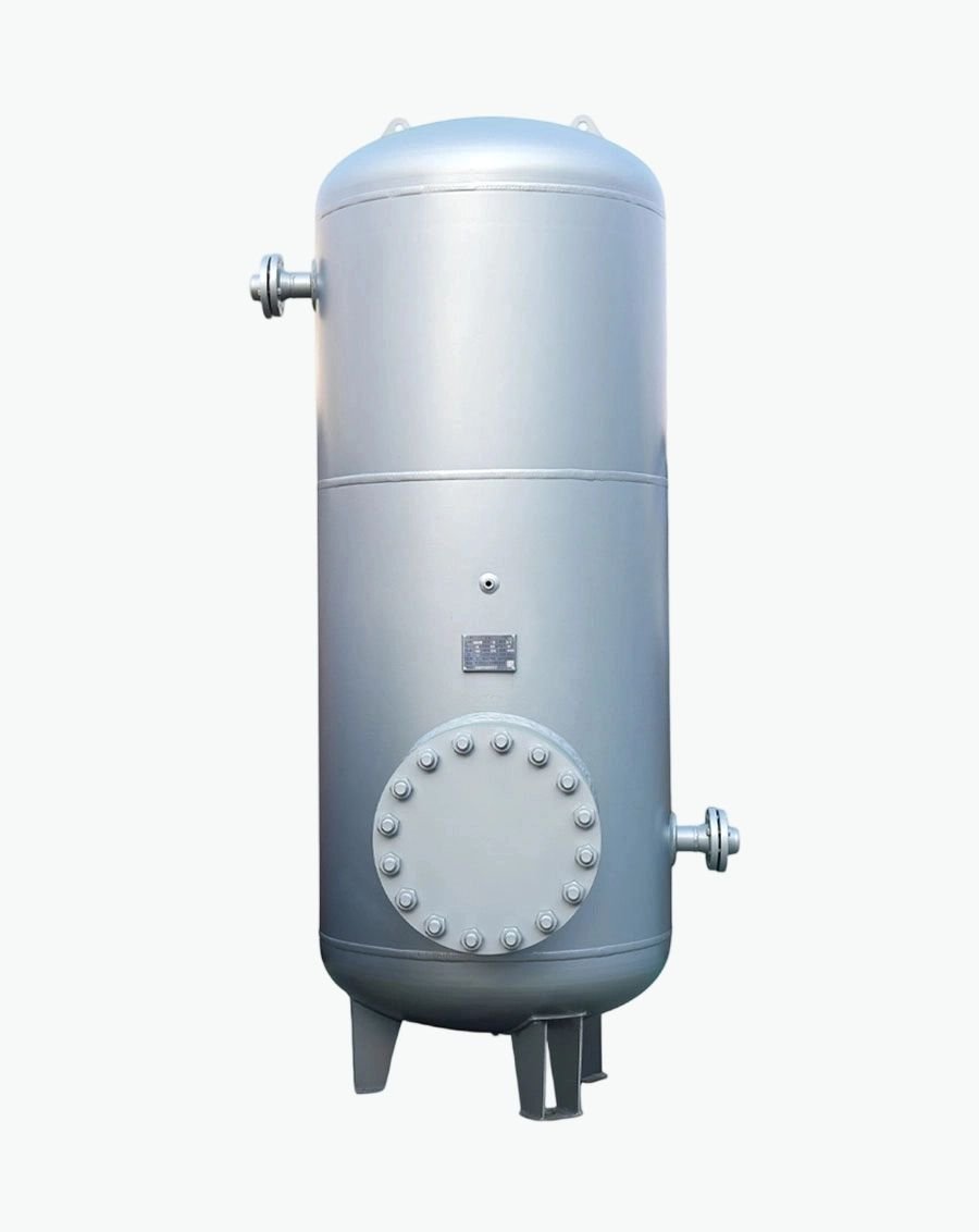
Platform vendors specify the rack, the cold plates and the CDU. Nobody specifies the expansion vessel, the reservoir, the buffer tank or the deaeration equipment — until the loop cannot hold pressure, the cold plates foul, or the plant trips on every chiller restart.
Send us your platform (GB200 NVL72 / GB300 NVL72), rack count, CDU model, secondary loop volume, coolant specification, static height, safety valve setting and facility water conditions, and we will return a complete, calculated fluid management specification — vessels sized to EN 12828 / EN 13831 with PED or ASME conformity, materials selected against your actual water chemistry, and separation and deaeration equipment matched to your loop volume.

Specializing in pressure vessel manufacturing, we provide reliable, certified, and customized solutions for customers across diverse industries worldwide.
No.268 Xinda Road, High-tech Industrial Park, Longkou City,Shandong Province
Copyright © 2026 Yantai Xinglong Pressure Vessel Manufacturing Co., Ltd All Rights Reserved.




 عربي
عربي
 Español
 Русский
