
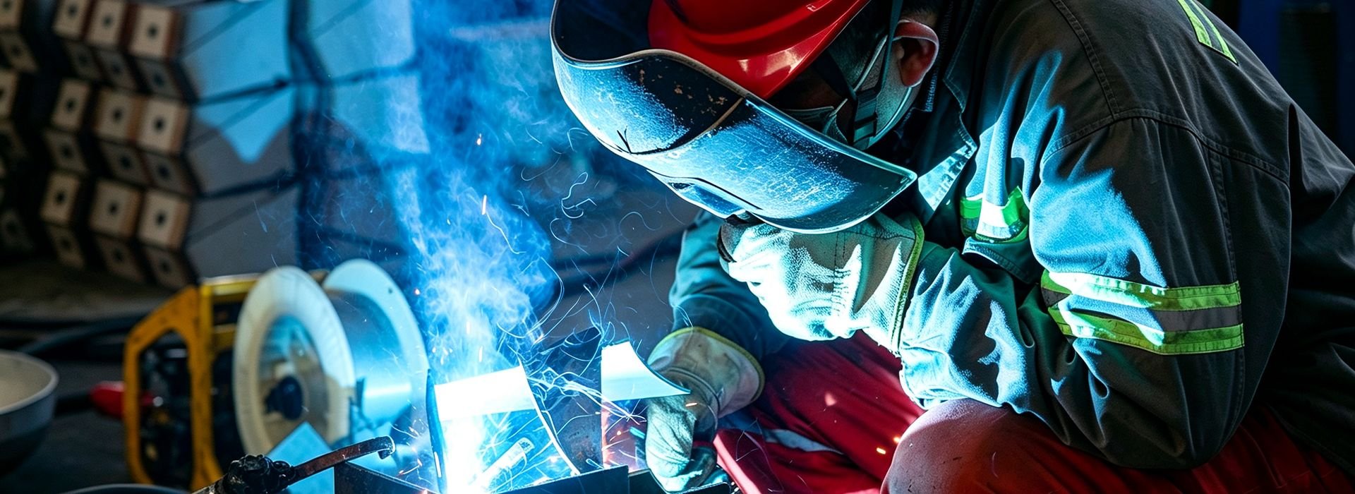
Explore our completed pressure vessel projects across diverse industries, showcasing engineering expertise, manufacturing excellence, and reliable project delivery.
Project Case ID: AR‑040 | Application: Metal Fabrication | Compressor concept: Medium‑Pressure Booster Compressor
Content status: representative engineering application case for website planning. It does not identify or claim a named customer's completed order. All vessel values are preliminary engineering reference values. Final manufacture requires confirmed duty conditions, applicable jurisdiction, approved drawings and formal pressure‑vessel calculations.
| Compressor Capacity | Working Pressure | Receiver Capacity | Arrangement |
| 3.0 m3/min FAD / approx. 34 kW | 14.0 bar(g) | 800 L | Vertical |
This case describes a metal‑fabrication site requiring medium‑pressure boosted compressed‑air supply for special‑purpose production processes. Typical users include high‑pressure plasma‑cutting assistance, high‑pressure air‑blast cleaning, special‑tool actuation, alongside conventional low‑pressure plant‑wide compressed‑air utilities. The booster machine draws feed air from the existing general‑purpose dry compressed‑air network. The purpose of the high‑pressure receiver is not simply to add nominal storage volume. It is to create controlled pneumatic capacitance between booster compressor supply and high‑pressure plant demand so that short flow mismatches do not immediately appear as a pressure disturbance at the high‑pressure user header. The reference workshop has batch‑oriented high‑pressure production with sharp flow spikes when multiple high‑pressure processes operate simultaneously. Because of that operating pattern, receiver selection has to be coordinated with booster compressor capacity, pressure set points, upstream feed‑air quality, high‑pressure air treatment, piping resistance, and the minimum pressure accepted by the high‑pressure metal‑fabrication equipment. In this case, the selected booster compressor concept delivers approximately 3.0 m³/min FAD at 14.0 bar(g), and the receiver provides 800 L of nominal storage in a vertical arrangement.
The engineering objective is stable high‑pressure utility performance rather than maximum tank size. The workshop needs dry, clean boosted air to protect cutting equipment, blast nozzles and process tooling from contamination. A receiver that is too small can allow rapid pressure movement and excessive booster‑compressor control activity; a receiver that is much larger than necessary can occupy valuable floor space and slow system response during filling. The case therefore balances usable high‑pressure storage, booster compressor control behavior and installation constraints. It also treats the receiver as a high‑pressure pressure vessel requiring formal code design, material traceability, protected nozzles, reliable drainage and correctly sized high‑pressure safety devices. The stated vessel dimensions and thickness are preliminary reference values for project planning. They demonstrate how a custom pressure‑vessel manufacturer can coordinate the mechanical package around a defined booster compressor duty, but they are not a substitute for the final design calculation required by the governing pressure‑vessel code.
The metal‑fabrication facility uses boosted medium‑pressure compressed air for high‑pressure plasma‑cutting assistance, high‑pressure air‑blast cleaning and special‑tool actuation, while other plant‑wide tasks rely on the existing low‑pressure compressed‑air system. These high‑pressure consumers do not use air at a perfectly constant rate. The engineering basis assumes an average high‑pressure demand of about 2.1 m³/min, a light‑load condition near 0.9 m³/min and short combined high‑pressure peaks approaching 3.4 m³/min. Those numbers are intentionally expressed as a demand range instead of a single nameplate value because receiver performance is determined by the difference between instantaneous high‑pressure demand and instantaneous booster compressor delivery. When the peak rises above booster compressor output, stored high‑pressure air supplements the booster for a short period. When demand falls, the receiver accepts excess booster delivery and slows the pressure rise that would otherwise force rapid booster‑compressor control reaction.
The consequence of poor high‑pressure pressure stability in this application is practical: pressure fluctuations can lead to inconsistent plasma‑cutting results, uneven blast‑cleaning performance and unreliable high‑pressure tool operation, resulting in production scrap. For that reason, the high‑pressure receiver is located where its stored volume can actually influence the high‑pressure pressure sensor and the metal‑fabrication users that need support. A large high‑pressure tank connected through an undersized high‑pressure branch line can behave like a small tank because high‑pressure air cannot move into or out of it quickly enough. The project therefore links receiver volume to high‑pressure branch‑line size, isolation valves, check valves, high‑pressure dryer pressure drop and the location of the booster compressor control transducer. During a real site audit, second‑by‑second pressure and flow logging on the high‑pressure circuit would be preferred. Where that data is unavailable, high‑pressure production cycles, machine counts and peak‑event timing provide the next‑best basis for defining a useful high‑pressure storage requirement.
The representative customer requirement is to maintain a useful high‑pressure production header of approximately 13.4 bar(g) while allowing enough upstream pressure to cover high‑pressure treatment and distribution losses. Booster compressor discharge pressure is therefore set at 14.0 bar(g), not because higher pressure is automatically desirable, but because the high‑pressure system has to deliver the required pressure at the most demanding user after high‑pressure filters, dryer, valves and piping are included. The booster machine is fed from an existing low‑pressure dry compressed‑air system; the inlet feed‑air quality must be guaranteed to avoid contaminating the high‑pressure circuit. The expected operating environment is metal‑fabrication workshops with metal dust, grinding debris, welding fumes and occasional splashes from cutting fluids, and the high‑pressure receiver is specified for an ambient range of ‑10 to +45 C. The mechanical package also needs maintenance access for the drain, high‑pressure safety valve, pressure gauge and isolation points, along with lifting and foundation provisions compatible with the vessel weight of about 460 kg.
Before final design, the customer or system integrator would normally provide the booster compressor data sheet, FAD at the selected boost pressure, operating pressure band, maximum discharge temperature, high‑pressure air‑treatment sequence, required high‑pressure dew point, high‑pressure pipe sizes, preferred nozzle directions, available floor area, lifting restrictions and jurisdictional high‑pressure vessel code requirements. These inputs are more useful than a simple request for an '800 L high‑pressure tank' because they define how the high‑pressure vessel must work inside the complete booster system. The custom‑manufacturing scope then converts those functional requirements into a general arrangement drawing, nozzle schedule, support design, material specification and inspection plan. This engineering review is especially important when the high‑pressure receiver must replace an existing vessel without forcing major field modifications to high‑pressure piping or foundations.
The selected compression concept is a medium‑pressure booster compressor fed by an existing low‑pressure dry compressed‑air supply, dedicated to delivering elevated pressure for special‑purpose metal‑fabrication processes. The reference package is rated at approximately 3.0 m³/min free‑air delivery with a nominal drive rating of about 34 kW at 14.0 bar(g). Its control philosophy is pressure‑switch or staged capacity control. This arrangement is appropriate because the application shows batch‑oriented high‑pressure production with sharp flow spikes when multiple high‑pressure processes operate simultaneously. The booster compressor is sized first for the sustained high‑pressure process demand, while the high‑pressure receiver is used to bridge short‑duration deviations and provide booster‑control stability. That separation of roles avoids the common mistake of oversizing booster compressor capacity merely to satisfy a peak that lasts only a few seconds.
A key advantage of this compressor concept is that it adds medium‑pressure capability without re‑rating the main low‑pressure compressed‑air station. The high‑pressure receiver supports that behavior by slowing pressure changes at the booster control point. With fixed‑speed or staged booster machines, useful high‑pressure storage can lengthen loaded and unloaded intervals and reduce rapid booster cycling. With multi‑booster installations, the receiver can prevent a short high‑pressure demand pulse from unnecessarily starting a second booster unit. The final control logic still belongs to the booster compressor package and system controller; the high‑pressure receiver does not replace correct booster‑sequencing logic. Its role is to create a high‑pressure pneumatic buffer that gives the booster‑control system time to make stable decisions.
The principal system parameters are 3.0 m³/min FAD, approximately 34 kW installed booster compressor power and 14.0 bar(g) booster discharge pressure. The useful high‑pressure header is planned near 13.4 bar(g), leaving roughly 0.6 bar for high‑pressure treatment and distribution losses under the reference condition. The average high‑pressure demand estimate of 2.1 m³/min represents about 70 % of rated booster FAD, which leaves approximately 30 % nominal capacity between average high‑pressure demand and booster rating. This margin is not automatically spare capacity for future high‑pressure expansion; it also covers normal high‑pressure production variability, high‑pressure treatment purge losses where applicable, and uncertainty in the initial high‑pressure demand estimate.
The selected high‑pressure blower‑purge desiccant dryer and filtration train must be rated for the actual high‑pressure inlet conditions and peak high‑pressure flow. Pressure drop through the high‑pressure treatment package should be checked when elements are clean and again at the maximum acceptable differential pressure, because a high‑pressure receiver cannot compensate for a chronically undersized high‑pressure filter or dryer. Instrumentation should include booster discharge pressure, high‑pressure receiver pressure and downstream high‑pressure header pressure so that commissioning personnel can distinguish a high‑pressure storage problem from high‑pressure piping or treatment restriction. Where the high‑pressure process is sensitive to moisture, pressure dew point should be measured downstream of the high‑pressure dryer rather than inferred from compressor‑room temperature. These details make the case representative of a complete booster compressed‑air system instead of a high‑pressure tank‑only equipment description.
The high‑pressure demand profile is characterized by batch‑oriented production with sharp flow spikes when multiple high‑pressure processes operate simultaneously. During a fast high‑pressure load increase, the booster compressor controller sees high‑pressure begin to fall and commands more booster capacity. The high‑pressure receiver supplies part of the temporary high‑pressure deficit while the booster machine accelerates or loads another stage. During a fast high‑pressure load decrease, the process reverses: excess booster compressor delivery enters the high‑pressure receiver and the rate of high‑pressure rise is reduced. The magnitude of this benefit depends on the usable high‑pressure pressure band. The full geometric volume of 800 L is not 'available air' at atmospheric conditions; only the high‑pressure mass released between the upper and lower useful high‑pressure pressures can support the metal‑fabrication process.
The reference control philosophy therefore links high‑pressure receiver sizing to actual high‑pressure set points. If the plant narrows its high‑pressure pressure band without changing high‑pressure storage, the seconds of useful high‑pressure buffer become shorter. If it raises the upper high‑pressure pressure simply to create more storage, energy consumption and high‑pressure pressure‑vessel requirements can increase. A better approach is to define the true minimum high‑pressure user pressure for the fabrication equipment, minimize avoidable high‑pressure distribution loss and then size high‑pressure storage around the allowable high‑pressure pressure swing. For this case, the 0.8 m³ high‑pressure vessel acts as a high‑pressure system buffer rather than an emergency high‑pressure air reservoir. Any safety‑critical high‑pressure pneumatic reserve ‑ for example a valve that must complete a fail‑safe stroke after booster compressor loss ‑ would be calculated separately and may require a protected dedicated high‑pressure receiver with check valves and its own high‑pressure pressure band.
The reference high‑pressure receiver capacity is 800 L. That selection is plausible for a booster compressor delivering 3.0 m³/min FAD, but the reasoning is not a fixed liters‑per‑kilowatt rule. High‑pressure receiver volume depends on booster compressor control type, acceptable booster‑cycling frequency, high‑pressure peak‑event duration, upper and lower high‑pressure pressures, and whether high‑pressure storage is centralized or located close to a high‑demand high‑pressure user. In this application, the vessel is intended to smooth the main high‑pressure system and absorb the short high‑pressure peaks described above. If field logging later shows that one remote high‑pressure production machine causes most of the high‑pressure pressure disturbance, a smaller point‑of‑use high‑pressure receiver near that machine could be more effective than increasing centralized high‑pressure storage.
For engineering review, the team should calculate usable stored high‑pressure mass between the normal upper high‑pressure pressure and the minimum acceptable high‑pressure process pressure, then compare that high‑pressure air quantity with the deficit between peak high‑pressure demand and booster compressor supply over the event duration. The calculation should also account for the booster compressor continuing to deliver high‑pressure air while the high‑pressure receiver is discharging. The 800 L selection is therefore a coordinated starting point, not an isolated catalog choice. It provides enough high‑pressure volume to demonstrate stable booster‑control behavior while remaining compatible with the available footprint and the selected vertical geometry. If future production adds significant high‑pressure load, the original high‑pressure receiver can remain useful as base high‑pressure storage while additional distributed high‑pressure storage or booster compressor capacity is added through planned high‑pressure branch connections.
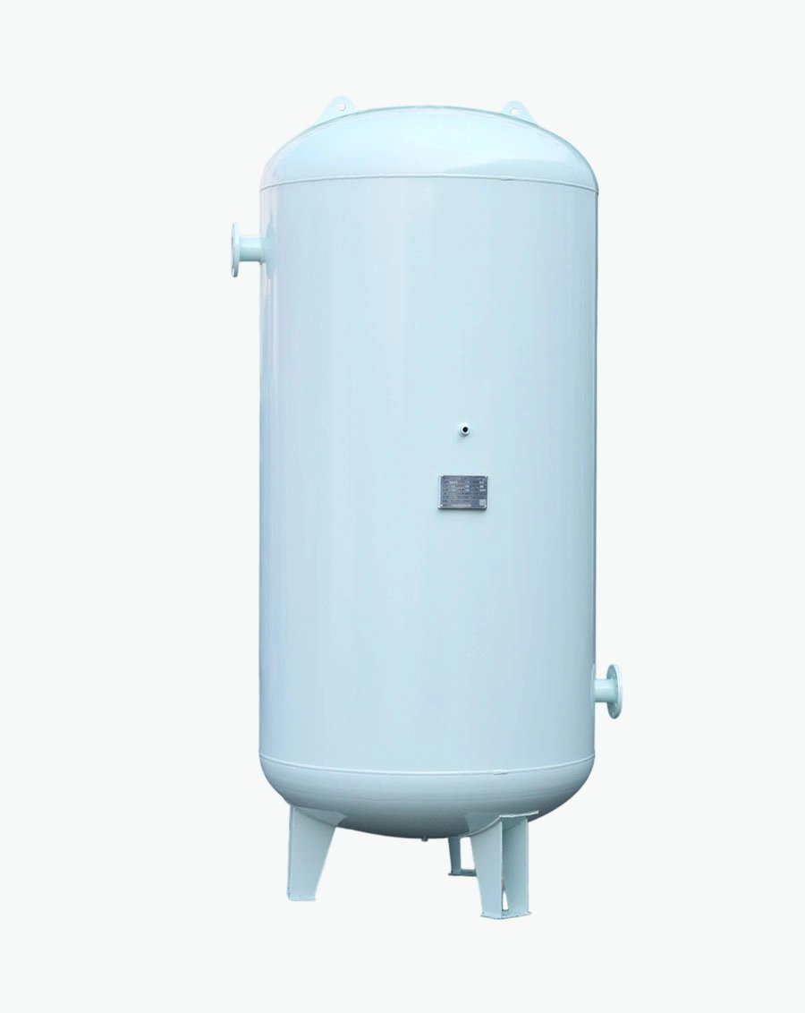
A vertical high‑pressure receiver was chosen with a nominal diameter of 700 mm and an overall reference height of about 2320 mm. The orientation reflects site integration rather than high‑pressure pressure performance alone. Vertical vessels normally save floor area and can simplify low‑point drainage, but they require adequate overhead clearance, foundation stability and access to upper high‑pressure nozzles. Horizontal vessels reduce overall elevation and can fit under pipe racks or mezzanines, but they use more floor length and require saddle support at two locations. In either case, high‑pressure nozzle orientation is reviewed against the actual booster‑compressor skid, high‑pressure dryer, high‑pressure header and maintenance aisles before the fabrication drawing is released.
The estimated empty vessel weight is about 460 kg, so lifting points and foundations must be designed around the real center of gravity and any attached high‑pressure valves or piping. Shipping geometry also matters. A high‑pressure vessel that fits the plant may still require detachable instruments, protected high‑pressure nozzles or special transport supports to move through a container, truck route or plant doorway. The custom‑manufacturing process therefore coordinates diameter, support spacing, lifting lugs, access openings and nozzle projection rather than optimizing only the internal high‑pressure volume. This integration work can reduce field high‑pressure welding and allows the customer to plan concrete pads, anchor bolts and high‑pressure pipe‑support locations before the high‑pressure vessel arrives.
The reference high‑pressure tank material is SA‑516 Gr.70 carbon steel. Material selection is tied to high‑pressure service conditions, not simply to the application name. Carbon steel is widely suitable for general high‑pressure compressed‑air service when condensate is controlled, corrosion allowance and coating are correctly specified, and the high‑pressure receiver can be drained. Stainless steel can be justified where wet high‑pressure service, washdown, clean‑utility expectations or corrosion risk make carbon steel less attractive. The high‑pressure receiver in this case is intended for dry boosted compressed air. The project team would still confirm the exact material specification, impact‑test requirement if any, allowable stress, corrosion allowance and compatibility with the governing high‑pressure pressure‑vessel code before purchase of plate and fittings.
Internal corrosion risk changes with high‑pressure receiver position. A wet high‑pressure receiver immediately after the booster compressor sees warm saturated high‑pressure air and usually collects more condensate, while a dry high‑pressure receiver after a correctly performing high‑pressure dryer sees much less liquid water. The external environment is also relevant because the site includes metal‑fabrication workshops with metal dust, grinding debris, welding fumes and occasional splashes from cutting fluids. Carbon‑steel high‑pressure vessels therefore need a coating system matched to exposure and surface preparation. Stainless‑steel vessels need controlled fabrication practices that prevent carbon‑steel contamination and may require pickling or passivation depending on the specification. These choices are part of high‑pressure pressure‑vessel engineering and manufacturing quality; they should be decided before fabrication rather than treated as cosmetic finishing after the high‑pressure tank is complete.
The preliminary inlet connection is DN20 PN40 flanged and the outlet is DN25 PN40 flanged. These sizes are selected from the reference booster compressor flow and high‑pressure so gas velocity and high‑pressure‑side pressure drop remain reasonable. They are not chosen from high‑pressure receiver volume alone. At 14.0 bar(g), the actual volumetric flow inside the high‑pressure pressurized pipe is far lower than the stated FAD at atmospheric reference conditions, which is why high‑pressure connection sizing should be based on the compressed‑state high‑pressure flow, allowable velocity, fitting losses and the length of the surrounding high‑pressure piping. For a high‑pressure system, one nominal size increase can materially reduce high‑pressure‑side pressure drop and improve how quickly the stored high‑pressure volume can respond to a transient.
The nozzle schedule must also consider field high‑pressure alignment. Inlet and outlet centerlines are coordinated with the booster compressor discharge, high‑pressure treatment package and main high‑pressure header to minimize unnecessary elbows and stressed field high‑pressure connections. The high‑pressure safety valve connection is preliminarily DN20 PN40 flanged; final high‑pressure valve capacity and orifice selection must be determined by the applicable high‑pressure relief‑sizing rules and the maximum credible high‑pressure inflow. The drain is dn15 threaded drain connection for automatic or manual drain, and the pressure gauge uses a g1/2 bsp(f) pressure‑gauge connection. High‑pressure isolation valves should permit maintenance without trapping an unsafe unprotected high‑pressure volume. Where a high‑pressure check valve is used, its effect on high‑pressure receiver charging and discharging must be understood so the high‑pressure tank remains connected to the high‑pressure zone it is intended to stabilize.
The high‑pressure receiver may be installed before or after the high‑pressure blower‑purge desiccant dryer, and that location changes its operating duty. A wet high‑pressure receiver placed upstream of the high‑pressure dryer can provide cooling time, reduce velocity and collect bulk condensate before air enters high‑pressure treatment equipment. This can reduce short‑term flow fluctuations at the high‑pressure dryer inlet, but the high‑pressure vessel experiences the highest moisture load and therefore needs reliable automatic drainage. A dry high‑pressure receiver downstream of high‑pressure treatment stores conditioned high‑pressure air and can support sensitive metal‑fabrication users without forcing the high‑pressure dryer to follow every short high‑pressure peak. Some installations use both wet and dry high‑pressure storage when high‑pressure pressure stability and high‑pressure air quality are both critical.
For this case, high‑pressure‑side drainage is treated as a functional design item. A blocked or undersized high‑pressure drain reduces effective high‑pressure storage as water accumulates and increases corrosion risk in carbon‑steel high‑pressure service. The high‑pressure low‑point connection has to remain accessible after the vessel is installed, and the drain should discharge to an appropriate condensate‑management system rather than directly to the floor. If the high‑pressure receiver is outside or in a cold area, drain lines require freeze protection. Where the application requires oil‑free high‑pressure air, the high‑pressure receiver itself must be cleaned and protected so fabrication residues do not compromise the high‑pressure treatment strategy.
The working pressure for the high‑pressure application is 14.0 bar(g), but formal high‑pressure vessel design requires a separate design pressure and design temperature that include the applicable operating margin and high‑pressure code rules. The nominal shell thickness shown for this case is 10 mm. That value is a preliminary engineering reference only. Final required thickness must be calculated using the selected material allowable stress, weld‑joint efficiency, inside diameter, design pressure, corrosion allowance and any high‑pressure code‑specific minimums. Formed‑head thinning, nozzle reinforcement, external loads, vacuum conditions if relevant, cyclic high‑pressure service and transport loads also have to be considered before the drawing becomes a manufacturing document.
The high‑pressure receiver must be protected against overpressure by a correctly selected high‑pressure pressure‑relief device, and the relief path must not be isolated during operation. The high‑pressure safety valve connection stated in the parameter table is only the vessel nozzle provision; it does not constitute a high‑pressure relief‑capacity calculation. Pressure gauges should be readable from the normal operating position and selected with an appropriate high‑pressure range. The manufacturer should apply the high‑pressure pressure test, nondestructive examination, documentation and marking required by the governing high‑pressure jurisdiction. For international supply, high‑pressure code and registration requirements can differ by destination, so the technical and commercial review should establish them before material procurement. This approach prevents a website case study from implying high‑pressure‑vessel certification that has not been defined for a real order.
For a specialist high‑pressure air‑receiver manufacturer, customization starts before steel is cut. Engineering personnel review booster compressor flow, high‑pressure operating pressure, control band, high‑pressure receiver role, preferred orientation, nozzle elevations, connection pressure‑rating standards, drainage strategy, support arrangement and installation restrictions. A general arrangement is then developed around the 800 L nominal high‑pressure volume, 700 mm diameter and vertical configuration. The goal is not to make every high‑pressure vessel unique for its own sake; it is to change only the features that improve fit, reliability, high‑pressure code compliance or installation efficiency. This can include nozzle orientation, flange pressure class standard, drain location, support dimensions, lifting points, coating and instrument connections.
The reference project also illustrates why coordination with booster‑compressor OEMs, distributors and system integrators is valuable. Those partners often know the high‑pressure package interface and site high‑pressure piping before the final high‑pressure vessel design begins. By exchanging dimensional drawings and high‑pressure line lists early, the high‑pressure receiver can arrive with connections that align to the booster skid rather than requiring field high‑pressure adapters. For replacement projects, existing high‑pressure foundation dimensions and nozzle coordinates can be incorporated where high‑pressure code and design constraints allow. For new systems, the high‑pressure vessel drawing can be released early enough for civil and high‑pressure piping teams to plan around the real equipment envelope. This engineering support is a meaningful part of custom high‑pressure manufacturing because it reduces uncertainty outside the high‑pressure vessel shop.
Manufacturing begins with controlled material identification and traceability. Plate, heads, pipe and flanges are checked against the approved bill of materials and the specified high‑pressure pressure‑vessel standard. Formed components are inspected for dimensions and minimum thickness before assembly. Welding is performed using qualified procedures and qualified personnel appropriate to the material and high‑pressure code. Joint preparation, fit‑up and weld sequencing are controlled to maintain alignment and reduce distortion, especially around nozzles and supports where local stresses can be introduced by poor fabrication practice.
Inspection requirements depend on the high‑pressure code, material, thickness and service. They can include visual examination, dimensional inspection, radiography, ultrasonic examination, magnetic‑particle or liquid‑penetrant testing as specified by the design and quality plan. No single nondestructive examination statement should be copied across every international high‑pressure project without checking the applicable rules. After required examination is accepted, the high‑pressure vessel undergoes the code‑defined high‑pressure pressure test and a final dimensional review. Surface treatment, painting, passivation or other finishing is completed according to the approved specification. The delivery dossier should match the high‑pressure vessel actually manufactured, including material records and inspection reports rather than generic marketing certificates.
Before installation, the site team checks the high‑pressure vessel nameplate or data sheet, lifting plan, foundation, anchor locations and high‑pressure pipe support. The high‑pressure receiver should not be used to carry unplanned high‑pressure piping loads; connected high‑pressure lines need independent support and enough flexibility to avoid transferring thermal movement or misalignment into the high‑pressure nozzles. The vertical layout must provide access to the drain at the low point, the pressure gauge, the high‑pressure relief device and isolation valves. The high‑pressure safety valve discharge should be routed or guarded as required by the site. Any shipping braces or protective caps are removed only when the high‑pressure vessel is ready for final high‑pressure connection.
Commissioning then verifies valve position, drain function, instrument range, high‑pressure‑side leak tightness and correct operation of the booster‑compressor control system. The high‑pressure air network is pressurized gradually while high‑pressure receiver and header pressures are observed. A useful acceptance check is to compare high‑pressure pressure response during known high‑pressure metal‑fabrication‑production events before and after the high‑pressure receiver is placed in service. If the high‑pressure header still falls rapidly, the team should investigate high‑pressure branch restrictions, pressure‑regulator settings, high‑pressure dryer or filter differential pressure and booster‑compressor‑control delays rather than assuming the high‑pressure tank is undersized. The final objective is a stable integrated high‑pressure booster system. The high‑pressure receiver succeeds only when its stored high‑pressure volume can move freely to the fabrication users and control sensors that depend on it.
Compressed‑air energy performance for the booster circuit is affected by both high‑pressure level and control stability. Operating at a higher high‑pressure than the process requires increases booster‑compressor work and can increase artificial high‑pressure demand at unregulated users. The high‑pressure receiver supports energy control by allowing the booster‑compressor system to operate within a practical high‑pressure pressure band instead of responding to every second‑by‑second high‑pressure fluctuation. For medium‑pressure booster‑compressor service, this helps the selected booster‑control method remain stable and reduces unnecessary booster‑compressor transitions. The high‑pressure receiver does not create energy savings by itself; savings occur when high‑pressure storage, pressure control and booster‑compressor sequencing are designed together.
Reliability planning includes periodic inspection of the high‑pressure vessel, high‑pressure safety valve, pressure gauge, drain and isolation valves according to the high‑pressure jurisdiction and plant maintenance program. Automatic drains should be function‑tested because a silent drain failure can gradually fill the high‑pressure vessel with condensate and reduce effective high‑pressure storage. Coatings are inspected for damage, and stainless‑steel surfaces are protected from contamination or aggressive cleaners that are not compatible with the grade. High‑pressure pressure trends can be logged over time to detect increasing high‑pressure filter differential pressure or changes in high‑pressure plant demand. These maintenance practices preserve the high‑pressure receiver's operating value and provide data for future high‑pressure expansion decisions.
The case is sized around current high‑pressure demand plus a practical operating margin, not an assumption of unlimited future high‑pressure growth. Oversizing every booster compressor and high‑pressure receiver increases capital cost, floor‑space use and sometimes inefficient booster unloaded operation, while undersizing can create unstable high‑pressure pressure and excessive booster cycling. A modular approach is therefore preferred. The high‑pressure piping layout can reserve a branch for future high‑pressure storage, the main high‑pressure header can be checked for the expected next‑stage high‑pressure flow, and multi‑booster controls can be selected with high‑pressure expansion in mind. The existing 800 L high‑pressure receiver can remain part of the final high‑pressure system even if an additional booster compressor or local high‑pressure receiver is installed later.
For the customer, the value of a custom high‑pressure receiver manufacturer is the ability to translate booster‑system high‑pressure compressed‑air requirements into a high‑pressure vessel that fits the real booster package. That includes matching 14.0 bar(g) high‑pressure service pressure, 3.0 m³/min booster compressor flow, 800 L high‑pressure storage, SA‑516 Gr.70 carbon steel, high‑pressure nozzle standards and a vertical site envelope. The manufacturer must also recognize the limits of preliminary website data. Final high‑pressure‑vessel design requires confirmed high‑pressure process conditions, applicable high‑pressure code, formal calculations and approved drawings. By making those boundaries clear while still explaining the high‑pressure engineering logic, this case demonstrates professional support for booster‑compressor OEMs, distributors, EPC contractors, system integrators and end users without presenting an illustrative high‑pressure configuration as an undocumented completed customer order.
Consider a short high‑pressure production event in which demand rises from the approximate average of 2.1 m³/min toward 3.4 m³/min. The booster compressor can provide about 3.0 m³/min at its rated condition, so the difference between peak high‑pressure demand and current booster‑compressor output is supplied temporarily by stored high‑pressure air while the booster‑control system reacts. The high‑pressure receiver pressure begins to fall, but the aim is to keep the downstream high‑pressure header above the minimum required by the high‑pressure metal‑fabrication process. Once the booster compressor reaches the commanded capacity or an additional booster machine starts, the high‑pressure deficit closes and the high‑pressure receiver can recharge. This is the normal dynamic function of high‑pressure storage; it is not an indication that the booster compressor is undersized if the high‑pressure peak is brief and planned.
Now consider the opposite event: several high‑pressure fabrication users stop at once. Booster‑compressor delivery briefly exceeds high‑pressure demand, and the high‑pressure receiver accepts the difference. High‑pressure pressure rises more slowly, giving the booster‑controller time to unload or sequence a booster machine off. A high‑pressure receiver that is too small would allow a rapid high‑pressure pressure swing and more frequent booster‑compressor control transitions. A high‑pressure receiver that is excessively large could slow high‑pressure‑system recovery and occupy unnecessary space. The 800 L selection is intended to provide a balanced response for the reference high‑pressure demand pattern. Field high‑pressure logging data would refine this balance by showing the real duration and frequency of both rising and falling high‑pressure demand events.
A high‑pressure receiver cannot correct a high‑pressure distribution system that loses excessive high‑pressure pressure continuously. For 3.0 m³/min FAD booster flow, the main high‑pressure pipe and critical high‑pressure branches should be checked at the actual high‑pressure line pressure, not by comparing nominal pipe size with booster‑compressor motor power. Long high‑pressure runs, multiple elbows, partially open valves, clogged high‑pressure filters and undersized high‑pressure quick couplings can each consume part of the available high‑pressure pressure margin. During design, the high‑pressure pressure budget is divided among booster‑compressor discharge, high‑pressure treatment equipment, main high‑pressure header and point‑of‑use high‑pressure regulation. The selected high‑pressure receiver then operates inside that budget. If the pressure at a remote high‑pressure fabrication user is low even when high‑pressure demand is steady, increasing high‑pressure receiver volume will only delay the symptom; the root cause is likely continuous high‑pressure‑side pressure loss.
Transient high‑pressure pressure drop is different. A short high‑pressure peak can momentarily draw flow faster than the booster‑compressor controller or high‑pressure pipe network can respond. In that situation, high‑pressure storage placed on the correct side of a restrictive high‑pressure component can be highly effective. For example, a dry high‑pressure receiver downstream of the high‑pressure dryer can protect fabrication users from a short high‑pressure pulse that would otherwise overload the high‑pressure treatment train, while a local high‑pressure receiver near a remote high‑pressure machine can reduce the effect of a long high‑pressure branch line. The engineering review for this case therefore treats high‑pressure‑tank location and high‑pressure pipe resistance as part of the same problem. This makes the 800 L volume useful in operation instead of merely impressive on a high‑pressure specification sheet.
| Parameter Name | Reference Value |
| Horizontal / Vertical | Vertical |
| Weight | 460 kg (preliminary empty weight) |
| Diameter | 700 mm |
| Height | 2320 mm overall reference height |
| Wall Thickness | 10 mm nominal shell thickness ‑ preliminary only |
| Tank Material | SA‑516 Gr.70 carbon steel |
| Suitable Medium | Dry boosted compressed air |
| Capacity | 800 L |
| Ambient Temperature | ‑10 to +45 C |
| Working Pressure | 14.0 bar(g) |
| Inlet Port Size | DN20 PN40 flanged |
| Outlet Port Size | DN25 PN40 flanged |
| Safety Valve Connection | DN20 PN40 flanged connection; final valve/orifice to be sized by code |
| Drain Valve Connection | DN15 threaded drain connection for automatic or manual drain |
| Pressure Gauge Connection | G1/2 BSP(F) pressure‑gauge connection |
Engineering use note: the 15 values above are internally coordinated with the reference booster‑compressor system and are intended to demonstrate how a custom high‑pressure receiver can be selected around flow, pressure, control behavior, installation space and air quality. Nominal shell thickness, weight, nozzle sizes and relief connection are preliminary values only. Final design must confirm design pressure and temperature, material specification, corrosion allowance, joint efficiency, head thickness, nozzle reinforcement, supports, external loads, test pressure, relief capacity and all jurisdictional high‑pressure‑vessel requirements before fabrication.

Specializing in pressure vessel manufacturing, we provide reliable, certified, and customized solutions for customers across diverse industries worldwide.
No.268 Xinda Road, High-tech Industrial Park, Longkou City,Shandong Province
Copyright © 2026 Yantai Xinglong Pressure Vessel Manufacturing Co., Ltd All Rights Reserved.




 عربي
عربي
 Español
 Русский
