
Stay updated with the latest company news, product innovations, exhibition highlights, and industry trends. Explore valuable insights into pressure vessel technologies and global markets.
This is not a luxury component. In a genuinely sealed loop with no compressible volume, water heated from 10 °C to 40 °C has nowhere to go. Pressure rises until something gives — a relief valve lifts, a gasket weeps, or a pump seal fails. Cool the same loop back down and the pressure can fall below atmospheric, drawing air in through vents, gaskets and pump seals. Both failure modes are common, both are avoidable, and both are cheap to prevent at design stage and expensive to fix in a live AI cluster.
A conventional comfort‑cooling chilled water loop is a fairly forgiving system. An AI data center technology cooling system (TCS) is not. Three differences raise the stakes:
Much higher heat flux per unit of fluid volume. A single NVIDIA GB200 NVL72 rack dissipates on the order of 120‑132 kW, with peaks reported at 130‑140 kW, and the great majority of that heat is rejected directly into the secondary coolant loop through cold plates. The coolant mass in the rack‑side loop is small relative to the heat load, so temperature transients are fast and steep. A loop that swings 15 K in a few minutes during a training‑job ramp swings its volume by roughly 0.3‑0.4 % in the same time. That volume has to go somewhere.
Tight pressure and flow windows at the cold plate. Microchannel copper cold plates with channel widths around 200‑300 µm, and secondary‑loop filtration at 25 µm or finer, mean the loop is intolerant of two things: cavitation (vapour bubbles collapsing in the plate) and gas entrainment (bubbles blanketing heat‑transfer surfaces). Both are driven by low or unstable pressure at the pump suction — exactly what a correctly precharged expansion vessel prevents.
Condensation limits. Rack‑side coolant supply temperature is often specified between 18 °C and 32 °C for current Blackwell‑class hardware, which can sit close to or below the dew point of the white space. Pressure stability matters because it lets the control system hold supply temperature tightly (commonly ±0.5‑1 °C at the CDU) without the loop pressure drifting as a side effect.
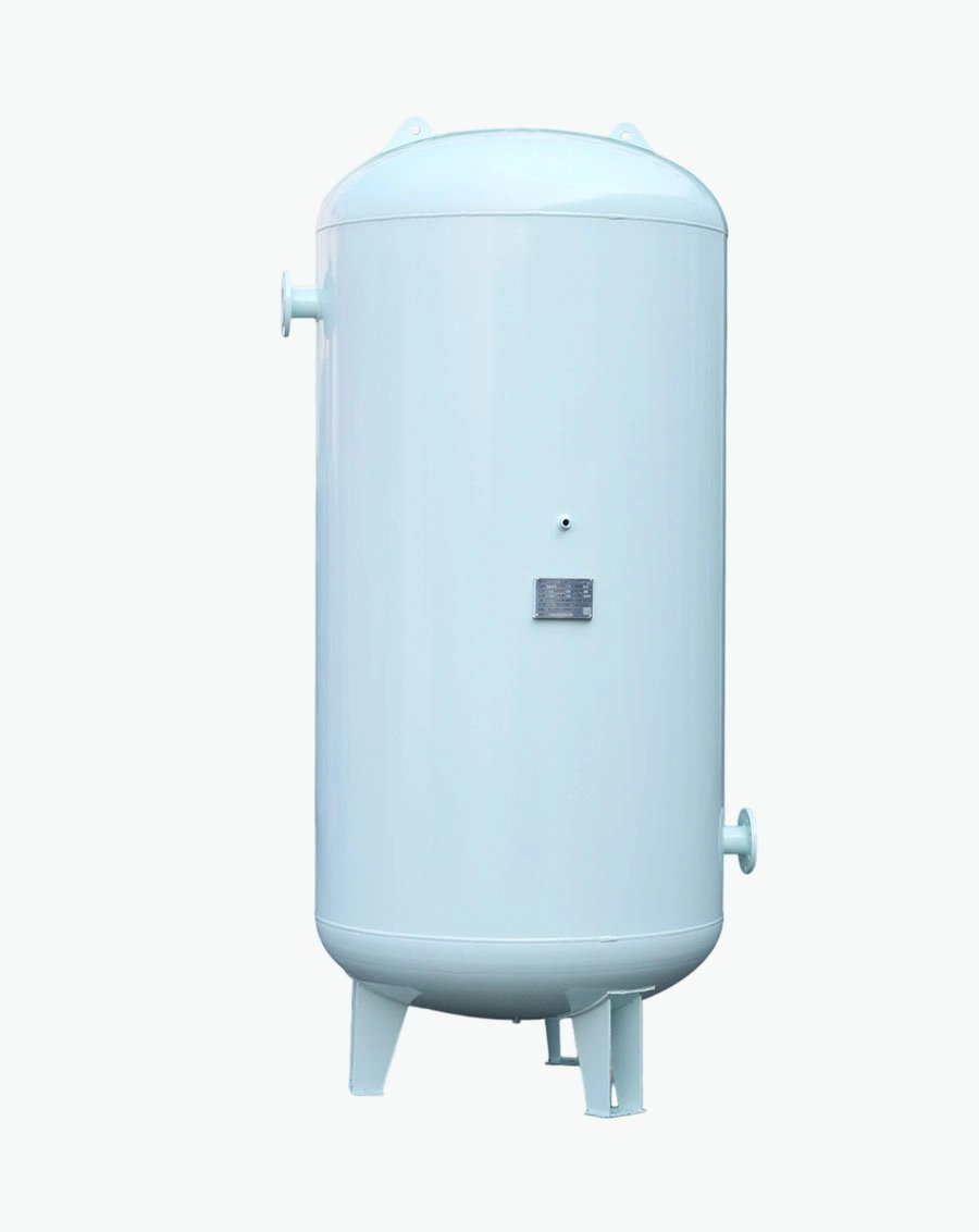
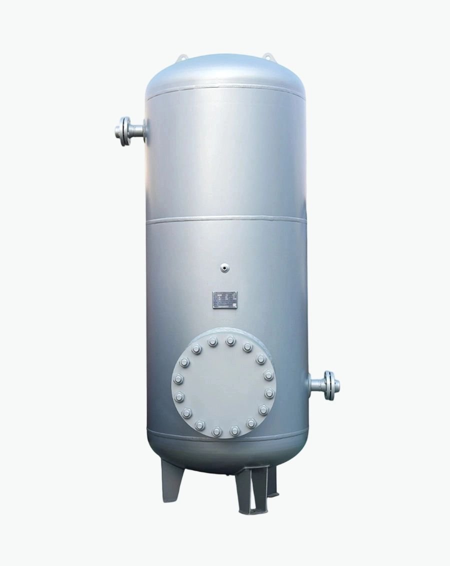
Absorbing thermal expansionCoolant density falls as temperature rises. The vessel accepts that extra volume so the rest of the loop sees essentially no pressure change. The accepted volume is called the acceptance volume or usable volume, and it is only a fraction of the vessel's nominal size.
Gas side: Nitrogen pre‑charge is preferred over air for long‑life installations.
FWS — Facility Water System (primary). Chiller plant, cooling towers or dry coolers, primary distribution, the CDU's primary‑side heat exchanger. Higher pressure, larger volume, water quality controlled to facility standards.
TCS — Technology Cooling System (secondary). CDU pumps, secondary distribution pipework, in‑rack manifolds, quick disconnects, cold plates, and the return. Cleaner, lower pressure, tightly controlled temperature, typically running PG25 (25 % propylene glycol with treated water and an inhibitor package).
Both sides need their own expansion provision. This is a point that is repeatedly missed in retrofit projects: an existing chilled water plant already has pressurization sized for the old load; adding a bank of CDUs creates a brand‑new sealed secondary circuit that has no pressurization at all until someone specifies it. The CDU's integral reservoir covers part of the requirement, but larger secondary loops — multiple racks on a shared row manifold — frequently need a dedicated external expansion vessel plus an air/dirt separation assembly.
Practically, the vessel should be piped to the return side, upstream of the circulating pump suction, on the coldest part of the loop. That location maximizes NPSH benefit, keeps the membrane at its lowest operating temperature (which extends membrane life), and puts the connection point where pressure is lowest and most stable.
| Standard | Scope | Why it matters to a buyer |
| EN 12828 | Design of water‑based heating/cooling systems in buildings | Sets the sizing method, minimum fill pressure, and the 0.5 % system‑volume water reserve |
| EN 13831 | Closed expansion vessels with built‑in diaphragm | Product standard covering design, manufacture and testing; addresses vessels from above 0.5 bar up to 30 bar |
| DIN 4807‑2 | Historic German standard for open and closed expansion vessels | Largely superseded by EN 13831; still referenced in older specifications |
| PED 2014/68/EU | EU Pressure Equipment Directive | Mandatory conformity assessment and CE marking for pressure equipment above 0.5 bar — non‑negotiable for EU installations |
\(P_{0} \geq H / 10+0.2\ \text{bar}\)
Commissioning check‑list for expansion vessels:
Measure the actual pre‑charge with the vessel isolated and drained — a gauge reading taken with the system full is the system pressure, not the pre‑charge.
Confirm fill pressure exceeds pre‑charge by the specified margin.
Confirm the safety valve setting is below the maximum allowable pressure of the weakest component in the loop (often the cold plate or the quick disconnect, not the pipework).
Record the values. Re‑check at the first scheduled service — gas permeation through elastomer membranes slowly reduces pre‑charge over years, and a top‑up is a five‑minute task.
These three are routinely conflated, and mixing them up produces badly specified plants.
Expansion vessel — sealed, gas‑precharged, diaphragm or bladder. Function: pressure control and expansion compensation. Volume: typically tens to a few hundred litres on the secondary side.
Coolant reservoir — usually a vented or breather‑capped tank with no membrane. Function: fluid inventory, deaeration dwell time, pump suction head, make‑up and level indication. Volume: commonly 50‑500 L per CDU depending on the number of racks served.
Buffer tank — a large, essentially membrane‑free vessel. Function: stored thermal capacity for ride‑through and hydraulic decoupling between primary and secondary circuits. Volume: thousands to tens of thousands of litres.
Many modern CDUs integrate a reservoir plus an expansion volume into a single secondary‑side assembly, which is why the terms get blurred. Understanding the underlying functions — not the labels — is what allows you to specify the right thing. Both distinctions are covered in detail in our companion articles Expansion Tank vs. Coolant Reservoir: What Is the Difference? and What Is a Buffer Tank in AI Data Center Cooling?
Sizing on water properties when the loop actually runs PG25. Glycol expands significantly more than water; pure propylene glycol has a volumetric expansion coefficient roughly 2.7× that of water at 20 °C, and a 25 % mixture typically expands about 1.3‑1.5× more than water over the same temperature rise.
Ignoring the 0.5 % water reserve required by EN 12828.
Using gauge pressures instead of absolute pressures in the sizing equation — a small arithmetic slip that undersizes the vessel by a large margin.
Setting fill pressure equal to pre‑charge, which disables the vessel.
Connecting the vessel to the discharge side of the pump, forfeiting the NPSH benefit.
Forgetting that the safety valve setting, not the design pressure, defines the final pressure \(P_f\) in the sizing equation.
No isolation valve and drain at the vessel connection, making every future pre‑charge check a drain‑down job.
Specifying an air vent but no air or dirt separator — the vessel manages pressure, it does not remove entrained gas or magnetite.
Overlooking membrane compatibility with the actual coolant, especially in glycol or synthetic‑hydrocarbon service.
Ordering a vessel with no declared PED or ASME conformity to save a few percent on the price.
What is the difference between an expansion vessel and an expansion tank?Nothing meaningful — the terms are used interchangeably in the industry. "Vessel" tends to imply a larger, code‑built unit; "tank" is more common in North American practice. Functionally they are identical.
Does a liquid‑cooled AI rack need its own expansion vessel?The CDU almost always provides secondary‑side expansion and reservoir volume. Whether you need an additional external vessel depends on total secondary loop volume, the number of racks on a shared manifold, static height, and the CDU manufacturer's stated limits. Ask the CDU vendor for the maximum supported external system volume; if your loop exceeds it, an external vessel is required.
Can I use an open vented tank instead?Only if you redesign around it. An open tank cannot hold positive pressure at the pump suction, cannot suppress gas release as effectively, allows continuous oxygen ingress (which drives corrosion), and exposes the coolant to contamination. Closed, pressurized loops are standard for AI cooling for good reasons.
How often should pre‑charge be checked?At commissioning, then at least annually as part of the preventive maintenance schedule. Gas‑side pressure slowly decays through the membrane.
What pressure rating should I specify?Set by the loop's maximum operating pressure plus margin, and bounded by the lowest‑rated component (often the cold plate or quick disconnect, rated around 2.4‑3.5 bar in secondary service). Common secondary‑side working pressures are in the 3‑6 bar range; the vessel must be rated above the safety valve setting.
Nitrogen or air pre‑charge?Nitrogen. It excludes oxygen and moisture from the gas chamber and gives more stable long‑term pressure retention.
If you are sizing pressurization and fluid management equipment for an AI liquid cooling deployment, the fastest route to a correct answer is three numbers: total system volume, cold‑fill and maximum operating temperature, and the coolant specification. With those, plus the static height and safety valve setting, a vessel can be selected and documented in a single calculation sheet.
Our engineering team prepares that calculation — including EN 12828 / EN 13831 compliance documentation, PED or ASME conformity route, and membrane material selection against your actual coolant — as standard on every quotation.

Specializing in pressure vessel manufacturing, we provide reliable, certified, and customized solutions for customers across diverse industries worldwide.
No.268 Xinda Road, High-tech Industrial Park, Longkou City,Shandong Province
Copyright © 2026 Yantai Xinglong Pressure Vessel Manufacturing Co., Ltd All Rights Reserved.




 عربي
عربي
 Español
 Русский
