
Stay updated with the latest company news, product innovations, exhibition highlights, and industry trends. Explore valuable insights into pressure vessel technologies and global markets.
Air receiver tanks function not as isolated components but as integral elements within comprehensive compressed air treatment systems encompassing compressors, aftercoolers, dryers, filters, and distribution networks. Optimal system performance requires careful integration of these components ensuring each element complements others rather than creating bottlenecks, inefficiencies, or quality compromises. Receiver tank positioning relative to dryers and filters significantly impacts moisture removal effectiveness, pressure stability, energy consumption, and final air quality delivered to end-use applications.
Misconfigured systems suffer from common problems including inadequate drying allowing condensate damage downstream equipment, excessive pressure drops wasting compression energy, filter overload from unremoved particulates reducing service life, and unstable pressures causing application inconsistencies. These issues compound increasing operating costs, maintenance burdens, and production disruptions far exceeding individual component shortcomings. Proper integration addresses systemic interactions optimizing overall performance rather than maximizing individual element specifications in isolation.
This comprehensive guide examines air receiver tank integration strategies with dryers and filters providing engineering principles, configuration options, sizing methodologies, and operational best practices. By understanding how component interactions affect system behavior, facility managers, engineering teams, and compressed air specialists design integrated solutions delivering reliable, efficient, high-quality compressed air meeting diverse application requirements while minimizing lifecycle costs.
Standard industrial compressed air systems follow sequential treatment stages addressing different contamination types:
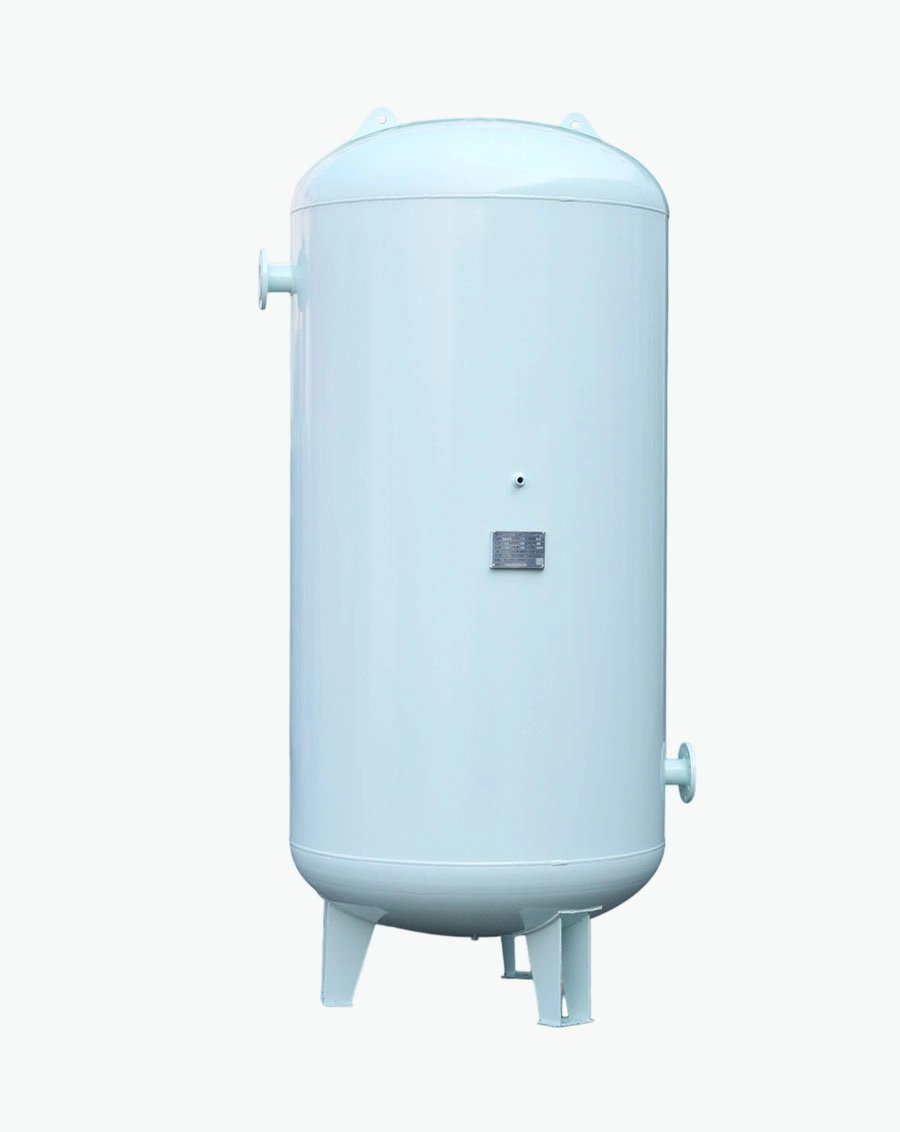
Stage 1 - Compression and Aftercooling: Ambient air drawn through intake filters enters compressors raising pressure 7-13 bar while generating substantial heat (discharge temperatures 80-150°C). Aftercoolers immediately reduce temperatures to 35-40°C promoting initial condensate separation removing 60-70% of water vapor. First receiver tanks (wet receivers) positioned here buffer compressor output and provide additional cooling residence time.
Stage 2 - Primary Separation: Wet receivers function as gravity separators allowing condensed water droplets settling to bottoms for drainage. Baffle plates or cyclonic inserts enhance separation efficiency creating swirling flows throwing droplets outward. Automatic drains remove accumulated condensate preventing re-entrainment. Outlet air remains saturated at aftercooler temperature containing significant remaining moisture.
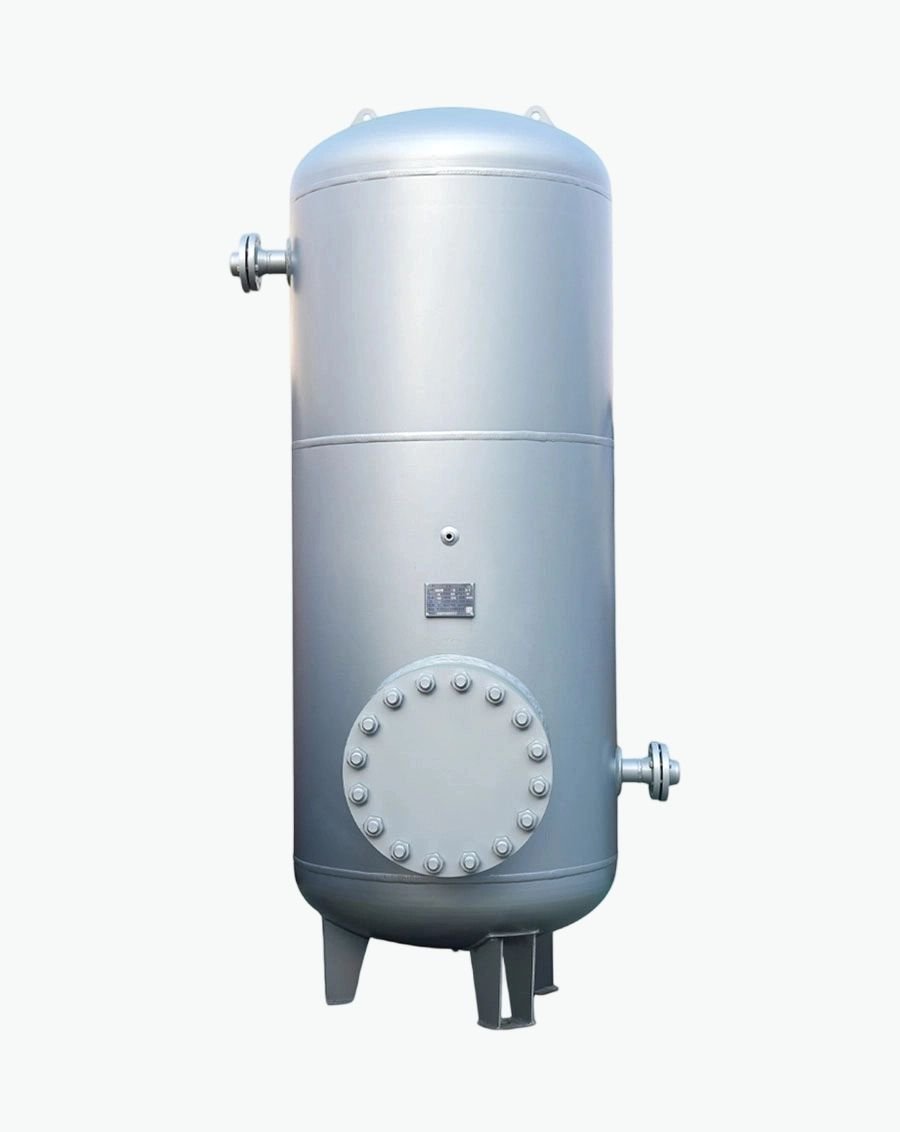
Stage 3 - Drying: Refrigerated or desiccant dryers further reduce moisture content achieving specified dew points. Refrigerated units cool air to 3-5°C removing additional 25-30% moisture suitable for general industrial use. Desiccant dryers reach -40°C or below serving critical applications though consuming regeneration energy. Second receiver tanks (dry receivers) positioned after dryers stabilize pressure and provide storage without reintroducing moisture.
Stage 4 - Filtration: Particulate filters remove solid contaminants (pipe scale, rust particles, compressor wear debris) while coalescing filters capture aerosolized lubricants and remaining water mist. Activated carbonadsorbers eliminate oil vapors and odors for sensitive applications. Filter sequencing progresses from coarse (40 micron) to fine (0.01 micron) protecting expensive final stages from premature loading.
Stage 5 - Distribution: Treated air enters distribution piping networks delivering to point-of-use applications. Additional point-of-use filters provide final polishing for critical processes. Pressure regulators adjust levels matching specific equipment requirements. Lubricators add controlled oil mist for pneumatic tool operation though increasingly replaced by oil-free alternatives.
Understanding this architecture reveals receiver tank roles at multiple stages requiring different specifications and integration approaches.
System elements interact creating emergent behaviors beyond individual capabilities:
Pressure Drop Accumulation: Each component introduces flow resistance consuming compression energy. Typical pressure drops include: aftercooler 0.1-0.3 bar, receiver tank 0.05-0.1 bar, dryer 0.2-0.5 bar, filters 0.1-0.3 bar each, distribution piping 0.2-0.5 bar. Cumulative drops reach 1-2 bar requiring compressors maintain higher discharge pressures increasing energy consumption approximately 7% per bar.
Optimization minimizes total pressure drop through proper sizing, strategic component placement, and regular maintenance preventing fouling. Undersized filters load quickly increasing differential pressures wasting energy. Clogged dryer heat exchangers reduce cooling effectiveness compromising dew point performance. Monitoring individual component pressure drops identifies maintenance needs before efficiency degrades substantially.
Moisture Management Cascading: Inadequate upstream moisture removal overloads downstream components extending beyond intended capabilities. Wet receivers failing to remove sufficient condensate flood refrigerated dryers reducing capacity and potentially damaging compressors.
Saturated air entering desiccant dryers saturates media rapidly requiring frequent regeneration cycles wasting energy. Water carryover into filters creates emulsions blocking pores increasing pressure drops.
Proper sequencing ensures each stage handles manageable moisture loads within design parameters. Interstage receivers between dryers and filters provide additional condensation opportunities protecting final filtration. Drain systems throughout prevent accumulation compromising subsequent treatment effectiveness. Monitoring dew points at multiple locations verifies treatment adequacy identifying failures early.
Thermal Interactions: Temperature changes throughout systems affect moisture holding capacity following psychrometric relationships. Hot air holds more vapor than cool air meaning identical absolute moisture contents represent different relative humidities at varying temperatures. Cooling promotes condensation removing moisture though requiring adequate drainage preventing re-evaporation during subsequent heating.
Heat recovery systems capturing compression waste heat may warm dried air reducing relative humidity though not adding moisture. This proves beneficial preventing downstream condensation if temperatures drop below dew points. However, excessive reheating wastes energy without proportional benefits. Thermal insulation maintains temperatures preventing unwanted condensation in distribution piping during cold weather.
Flow Dynamics and Pulsation: Compressor discharge exhibits pulsating flows particularly from reciprocating units creating pressure fluctuations stressing downstream components. Receiver tanks dampen pulsations providing steady flows improving dryer and filter performance. Screw compressors produce smoother outputs though still benefiting from buffering.
Turbulent flows enhance mixing promoting uniform treatment though increasing pressure drops. Laminar flows reduce resistance though potentially creating stratification with uneven moisture distribution. Pipe sizing affects velocities with optimal ranges (6-9 m/s) balancing pressure drop against erosion risks. Receiver tank inlet diffusers reduce velocities promoting condensate separation.
Positioning receivers before dryers serves multiple functions requiring specific design considerations: Primary Functions:
● Buffer compressor output smoothing flow variations
● Provide residence time for additional cooling and condensate separation
● Protect dryers from liquid slugs damaging heat exchangers or desiccant beds
● Enable compressor optimization through load/unload cycling
Sizing Methodology: Wet receivers sized based on compressor capacity and desired damping characteristics. General guidelines recommend:
● Fixed-speed compressors: 10-15 liters per m³/min (1 gallon per CFM)
● Variable speed drives: 5-10 liters per m³/min (smaller due to modulation capability)
● Reciprocating compressors: 15-20 liters per m³/min (larger due to pulsation)
Larger volumes provide greater buffering though diminishing returns apply beyond certain thresholds. Dynamic simulation models optimize sizing balancing capital costs against performance benefits
considering actual demand patterns rather than rule-of-thumb averages.
Design Features: Inlet diffusers reduce velocities promoting droplet separation. Baffle plates create tortuous paths throwing water outward through centrifugal action. Sloped bottoms (minimum 2% gradient) direct condensate toward low-point drains. Multiple drain connections accommodate large volumes ensuring complete removal.
Material selection considers aggressive condensate composition including dissolved CO■ forming carbonic acid, compressor lubricant carryover creating oily films, and atmospheric pollutants. Internal epoxy coatings protect carbon steel though stainless steel eliminates coating maintenance. Drain valve sizing prevents restriction during rapid discharge events.
Integration Considerations: Proximity to compressors minimizes connecting pipe pressure drops though requires adequate clearance for maintenance access. Isolation valves enable receiver maintenance without compressor shutdown. Bypass lines allow temporary operation during servicing though risking untreated air entering dryers if not properly managed.
Instrumentation includes pressure gauges monitoring inlet/outlet differential indicating internal blockages. Temperature sensors track cooling effectiveness verifying aftercooler performance. Level indicators alert operators to drain failures preventing overflow. Automated monitoring feeds data to centralized systems enabling trend analysis.
Receivers positioned after dryers serve different purposes requiring distinct specifications:
Primary Functions:
● Store dried air preventing moisture reabsorption from downstream sources
● Buffer demand fluctuations maintaining stable pressure to applications
● Enable dryer optimization by providing storage during low-demand periods
● Serve as backup supply during dryer maintenance or regeneration cycles
Sizing Methodology: Dry receiver sizing balances storage capacity against space and cost constraints:
● General industrial: 7-10 liters per m³/min compressor capacity
● Critical applications: 15-25 liters per m³/min for enhanced stability
● VSD systems: 10-15 liters per m³/min accommodating modulation characteristics
Smaller volumes suffice when dryers provide continuous output though larger storage enables dryer cycling improving part-load efficiency. Desiccant dryers particularly benefit from storage allowing extended adsorption periods between regeneration cycles reducing energy consumption.
Design Features: Since air entering dry receivers contains minimal moisture, internal corrosion protection proves less critical though not unnecessary. Condensate still forms if temperatures drop below dew points requiring drainage provisions. Sloped bottoms and drain valves remain standard though discharge volumes decrease substantially compared to wet receivers.
Material selections may relax slightly though stainless steel still preferred for hygienic applications. Carbon steel with standard coatings suffices for general industrial service given reduced moisture exposure. Internal inspections occur less frequently though annual examinations maintain regulatory compliance.
Insulation prevents external condensation on receiver surfaces in humid environments maintaining aesthetics and preventing slip hazards. Heat tracing maintains temperatures above dew points in cold climates avoiding freeze damage. Ventilation around outdoor installations prevents heat buildup affecting air density.
Integration Considerations: Location between dryers and filters protects filtration from moisture overload extending service life. Proximity to distribution manifold minimizes pressure drops though requires coordination with other system components. Multiple outlet connections serve different pressure zones or redundancy requirements.
Check valves prevent backflow during maintenance isolating sections safely. Pressure relief valves sized per code requirements protecting against overpressure from thermal expansion or control failures. Instrumentation monitors pressure trends enabling leak detection through decay rate analysis.
Systems employing both wet and dry receivers optimize treatment though requiring careful coordination:
Advantages:
● Comprehensive moisture management addressing condensation at multiple stages
● Enhanced buffering capacity smoothing both compressor and demand variations
● Redundancy enabling maintenance without complete system shutdown
● Flexibility accommodating varying operating conditions and future expansions
Challenges:
● Increased capital costs from duplicate equipment
● Additional footprint requirements straining space-constrained facilities
● Complex control coordination preventing conflicting operations
● More maintenance points increasing ongoing labor requirements
Control Strategies: Automated systems coordinate receiver charging/discharging optimizing overall efficiency. During low demand, wet receiver charges storing compressed air while dryer operates at reduced capacity. Peak demands draw from both receivers supplementing real-time compression. Control algorithms predict demand patterns pre-positioning storage minimizing response delays.
Pressure setpoints differentiate wet and dry receivers preventing unintended flows. Wet receiver maintains slightly higher pressure encouraging forward flow through treatment train. Dry receiver setpoint matches distribution requirements avoiding unnecessary recompression. Differential pressure monitoring verifies proper sequencing detecting bypasses or blockages.
Drain coordination prevents simultaneous discharges overwhelming collection systems. Staggered timing spreads loads though requiring sophisticated controls. Flow meters quantify discharged volumes validating treatment effectiveness. Abnormal accumulations trigger investigations identifying upstream failures.
Application Suitability: Dual configurations prove worthwhile for:
● Large facilities (>100 m³/min compressor capacity) where optimization benefits justify costs
● Critical processes requiring maximum reliability and air quality
● Variable demand patterns benefiting from enhanced buffering
● Future expansion plans needing modular scalability
Smaller systems often achieve adequate performance with single receivers reducing complexity and costs. Cost-benefit analysis determines optimal configuration based on specific application requirements rather than universal prescriptions.
Refrigerated dryers dominate general industrial applications requiring 3-5°C pressure dew points:
Sizing Compatibility: Dryer capacity must match or exceed compressor output preventing bottleneck formation. Undersized dryers cannot remove moisture adequately allowing saturated air into distribution causing downstream problems. Oversized dryers cycle inefficiently wasting energy though providing margin for future expansion.
Receiver tank placement affects dryer sizing requirements. Large wet receivers remove substantial moisture upstream reducing dryer load enabling smaller selections. However, dryer must still handle worst-case scenarios including high ambient humidity and maximum compressor output. Safety factors of 10-20% accommodate variations though excessive margins waste capital.
Ambient temperature ratings specify maximum operating conditions (typically 40-45°C). Higher temperatures reduce cooling capacity requiring derating or oversized selections. Ventilated enclosures maintain acceptable temperatures though consuming floor space. Outdoor installations require weatherproof housings protecting components from rain and direct sunlight.
Pressure Drop Management: Refrigerated dryers introduce 0.2-0.5 bar pressure drops from heat exchanger resistance. Proper sizing minimizes drops though cannot eliminate them entirely. Parallel dryer arrangements split flows reducing individual pressure drops though adding complexity and cost. Regular maintenance prevents fouling increasing resistance over time.
Receiver tanks positioned immediately after dryers absorb pressure fluctuations preventing transmission to distribution systems. This stabilization improves application performance though adds another pressure drop component (0.05-0.1 bar). Total system pressure drop calculations include all components ensuring compressors maintain adequate discharge pressures.
Variable capacity dryers modulate cooling based on actual loads improving part-load efficiency.
Receivers buffer short-term variations allowing dryers operate at optimal points rather than constantly adjusting. Combined systems achieve superior efficiency compared to either technology alone though requiring coordinated controls.
Condensate Handling: Refrigerated dryers generate substantial condensate requiring robust drainage systems. Automatic drains remove liquid continuously though requiring regular testing verifying functionality. Zero-loss drains minimize air waste though adding cost and complexity. Drain line sizing prevents restriction during peak condensate production.
Receiver tanks downstream collect additional condensate forming as air warms approaching ambient temperatures. This secondary condensation requires separate drainage though volumes decrease substantially. Monitoring both dryer and receiver drains quantifies total moisture removal validating system performance.
Oil-water separators treat contaminated condensate meeting environmental discharge regulations. Direct sewer connections violate regulations in most jurisdictions requiring pretreatment verification. Regular maintenance prevents separator overload ensuring continued compliance. Documentation supports regulatory audits demonstrating responsible environmental stewardship.
Desiccant dryers achieve ultra-low dew points (-40°C or below) serving critical applications though requiring different integration approaches:
Regeneration Energy Impacts: Desiccant dryers consume significant energy regenerating saturated media through heated purge, blower purge, or heatless methods. Receiver storage enables extended adsorption periods between regeneration cycles improving efficiency. Larger dry receivers allow longer adsorption times reducing regeneration frequency though requiring careful sizing preventing media saturation.
Heat of compression dryers utilize hot compressor discharge directly regenerating desiccant eliminating separate heating energy. This integration requires wet receiver positioning before dryer providing cooling residence time while maintaining sufficient temperature for regeneration. Control systems coordinate compressor loading with dryer regeneration optimizing overall efficiency.
Blower purge dryers use external blowers forcing ambient air through desiccant beds reducing compressed air waste compared to heatless designs. Receiver storage buffers pressure dips during purge cycles maintaining stable distribution pressure. Sizing accounts for purge flow requirements ensuring adequate supply during regeneration.
Tower Switching Dynamics: Dual-tower desiccant dryers alternate between adsorption and regeneration creating periodic pressure fluctuations. Receiver tanks absorb these transients preventing transmission to sensitive applications. Adequate storage volume maintains pressure within acceptable bands during switching transitions typically lasting 30-60 seconds.
Check valves prevent backflow during tower switching though introducing additional pressure drops. Soft-start controls gradually transition flows minimizing disturbances. Monitoring pressure trends verifies proper switching detecting valve failures or timing errors. Alarm systems alert operators to abnormalities requiring investigation.
Pre-Filtration Requirements: Desiccant media susceptible to contamination from particulates and liquids requiring robust upstream protection. Wet receivers remove bulk condensate though fine mist passes through necessitating coalescing filters before dryer inlet. Filter specifications typically 1 micron removing particles and aerosols protecting desiccant integrity.
Filter maintenance proves critical as loaded filters increase pressure drops wasting energy while allowing breakthrough contaminating desiccant. Differential pressure monitoring alerts when replacement needed preventing unexpected failures. Spare filter inventory enables timely changes avoiding extended downtimes.
Oil carryover from lubricated compressors coats desiccant reducing adsorption capacity permanently. Oil-free compressors eliminate this risk though commanding premium prices. Coalescing filters with oil removal capabilities provide partial protection though not complete elimination. Regular desiccant testing monitors condition replacing media before performance degrades unacceptably.
Post-Filtration Needs: Desiccant dust shedding during regeneration requires downstream particulate filters preventing contamination of distribution systems and applications. Filter
specifications typically 0.01 micron capturing fine particles though adding pressure drops. Activated carbon filters remove any oil vapors passing through desiccant beds though primarily relevant for lubricated compressor systems.
Filter positioning balances protection against pressure drop accumulation. Immediate post-dryer placement protects downstream components though requiring frequent changes if desiccant degradation accelerates. Point-of-use filters provide localized protection though multiplying maintenance points. System-wide filtration strategy optimizes locations balancing coverage against complexity.
Effective filtration employs progressive refinement protecting expensive final stages:
Stage 1 - Particulate Filters (40-5 micron): Remove solid contaminants including pipe scale, rust particles, compressor wear debris, and installation residues. Coarse filtration protects downstream components from abrasive damage extending service life. Pressure drops remain low (0.05-0.1 bar) when clean though increase as filters load requiring monitoring.
Element materials include pleated paper, synthetic fibers, or sintered metals depending on temperature and chemical compatibility requirements. Disposable elements prove economical for general service though reusable metallic filters suit harsh environments despite higher initial costs. Automatic self-cleaning filters reduce maintenance though adding complexity and costs.
Installation locations typically after wet receivers removing bulk moisture though before dryers preventing particulate damage to heat exchangers. Multiple parallel filters split flows reducing individual pressure drops though requiring valving for isolation during maintenance. Bypass arrangements enable temporary operation during filter changes though risking unprotected air entering sensitive components.
Stage 2 - Coalescing Filters (1-0.01 micron): Capture aerosolized lubricants, fine water mist, and submicron particulates through impaction and interception mechanisms. Coalesced droplets grow large enough draining by gravity collecting in filter bowls for automatic removal. Efficiency reaches 99.9% for particles >0.01 micron though pressure drops increase (0.2-0.4 bar) reflecting finer filtration.
Element designs incorporate hydrophobic materials repelling water while capturing oil aerosols. Temperature limits restrict applications though typically adequate for compressed air service. Pre-filtration protects coalescing elements from heavy loading extending service life. Differential pressure indicators signal replacement needs preventing breakthrough.
Positioning after dryers ensures minimal liquid water reaching coalescing filters preventing flooding and emulsion formation. Some configurations place coalescing filters before dryers removing oil aerosols that could coat heat exchangers reducing efficiency. Trade-offs depend on specific contamination profiles and priority protection targets.
Stage 3 - Adsorption Filters (Activated Carbon): Remove oil vapors, odors, and hydrocarbon gases through adsorption onto porous carbon surfaces. Capacity depends on carbon volume, contact time, and contaminant concentrations. Pressure drops remain moderate (0.1-0.2 bar) though increasing as carbon saturates requiring replacement.
Applications requiring ISO 8573-1 Class 1 oil content (<0.01 mg/m³) mandate activated carbon filtration regardless of upstream oil-free compression. Trace lubricant vapors from compressor seals or ambient air ingestion necessitate final polishing. Food, pharmaceutical, and electronics industries particularly value vapor removal preventing product contamination.
Temperature limitations (typically <50°C) require adequate upstream cooling preventing carbon degradation. Moisture reduces adsorption capacity requiring effective pre-drying. Regular replacement schedules prevent breakthrough though testing effluent quality verifies performance.
Spent carbon disposal follows hazardous waste regulations if oil-laden requiring proper handling.
Stage 4 - Sterile Filters (0.01-0.003 micron): Healthcare, food, and semiconductor applications require bacterial removal through membrane filters achieving absolute retention ratings. Hydrophobic PTFE membranes prevent water passage while blocking microorganisms. Integrity testing validates filter performance before and after use ensuring no bypass defects.
Steam-in-place capabilities enable sterilization without filter removal though requiring compatible construction materials. Single-use cartridges eliminate cleaning validation though generating waste. Multiple redundant filters provide backup preventing single-point failures compromising sterile air supply. Monitoring pressure drops detects loading requiring replacement before integrity compromises.
Extreme care during installation prevents contamination introducing organisms bypassing filtration. Cleanroom procedures govern filter handling maintaining sterility. Documentation supports regulatory audits demonstrating controlled processes. Training ensures personnel understand criticality following proper protocols consistently.
Proper filter sizing balances performance against pressure drop and cost:
Flow Capacity Ratings: Manufacturers specify maximum flow rates at defined inlet pressures and pressure drops. Actual capacity varies with operating conditions requiring correction factors for temperature, altitude, and inlet pressure deviations. Undersized filters overload quickly increasing pressure drops and reducing service life. Oversized filters waste capital though providing margin for future expansion.
Safety factors of 20-30% accommodate flow variations and gradual loading though excessive margins waste resources. Peak flow requirements determine sizing rather than average flows preventing bottleneck formation during high-demand periods. Multiple parallel filters split loads reducing individual pressure drops though adding complexity.
Contaminant Loading Estimates: Anticipated contamination levels influence element selection and change intervals. Dirty environments (foundries, woodworking shops) require robust pre-filtration protecting expensive final stages. Clean facilities (electronics, pharmaceuticals) extend element life though still requiring regular maintenance. Historical data from similar applications provides baseline estimates though site specific monitoring refines predictions.
Particle counting measures actual contamination levels guiding filter specification. Oil mist detectors quantify aerosol concentrations determining coalescing filter requirements. Dew point measurements verify drying effectiveness indicating moisture-related loading risks. Continuous monitoring enables predictive maintenance replacing elements based on actual condition rather than fixed schedules.
Pressure Drop Budgets: Total system pressure drop allocations distribute among components optimizing overall efficiency. Filters typically receive 0.3-0.5 bar budget across all stages requiring careful selection preventing excessive consumption. Initial clean pressure drops prove misleading as loaded filters increase resistance substantially. End-of-life pressure drops determine true energy impacts requiring lifecycle analysis.
Variable flow systems experience changing pressure drops complicating optimization. Maximum flow conditions create highest drops though occurring infrequently. Average flow pressure drops better
represent typical energy consumption though peak capacity must remain available. Simulation models predict pressure drop trajectories enabling informed selections balancing competing objectives.
Sustained filter performance requires disciplined maintenance programs:
Replacement Schedules: Time-based replacement provides simplicity though potentially changing elements prematurely or allowing breakthrough if loading accelerates. Condition-based replacement using differential pressure monitoring optimizes timing though requiring instrumentation investment. Hybrid approaches combine maximum time intervals with pressure triggers ensuring neither extreme occurs.
Typical service intervals range 3-12 months depending on contamination levels though actual variation proves substantial. Critical applications replace more frequently preventing any breakthrough risk. Non-critical services extend intervals accepting minor quality variations.
Documentation tracks replacement history identifying trends requiring investigation.
Differential Pressure Monitoring: Gauges or transmitters measure pressure drops across filters indicating loading status. Visual gauges provide local readings though requiring manual observation. Electronic transmitters feed data to monitoring systems enabling remote tracking and alarm generation. Trend analysis predicts remaining life scheduling replacements proactively.
Alarm setpoints trigger notifications when pressure drops exceed thresholds indicating imminent breakthrough. Escalation policies ensure timely responses preventing extended unprotected
operation. Automatic shutdown prevents contaminated air reaching critical applications though risking production disruptions. Balance between protection and continuity requires careful calibration.
Integrity Testing: Sterile filters require regular integrity testing verifying no defects allow microbial passage. Bubble point tests measure membrane strength though proving destructive.
Non-destructive methods include pressure hold tests detecting leaks through decay rates. Forward flow tests quantify actual retention performance though requiring specialized equipment.
Testing frequency depends on criticality with healthcare applications demanding monthly verification while industrial services accept annual checks. Documentation supports regulatory compliance demonstrating controlled processes. Failed tests trigger immediate replacement and root cause analysis preventing recurrence. Investigation determines whether failures result from manufacturing defects, installation damage, or operational abuse.
Disposal Considerations: Spent filter elements contain captured contaminants requiring appropriate disposal methods. Oil-laden filters classify as hazardous waste needing certified handlers following environmental regulations. Particulate filters may qualify as general industrial waste though local rules vary. Recycling programs recover metallic components though economic viability depends on commodity prices.
Documentation tracks disposal ensuring regulatory compliance. Vendor take-back programs simplify logistics though potentially increasing costs. On-site consolidation reduces transportation frequencies though requiring storage space. Environmental stewardship extends beyond operations encompassing end-of-life responsibilities demonstrating corporate citizenship.
Modern compressed air systems employ unified control platforms coordinating all components:
Data Aggregation: Sensors throughout systems collect pressure, temperature, flow, dew point, and power consumption data transmitting to central servers. Cloud-based platforms enable remote access facilitating multi-site monitoring and benchmarking. Local servers provide redundancy maintaining functionality during internet outages though requiring IT infrastructure support.
Historical databases store years of operational data enabling trend analysis and performance optimization. Data compression techniques manage storage volumes retaining high-resolution recent data while archiving older records at lower resolutions. Backup procedures prevent data loss ensuring continuity for compliance and diagnostic purposes.
Alarm Management: Intelligent alarm systems prioritize notifications based on severity preventing operator overload from minor deviations. Escalation policies route critical alarms to appropriate personnel ensuring timely responses. Acknowledgment workflows track accountability documenting actions taken. Root cause analysis tools correlate multiple alarms identifying underlying issues rather than treating symptoms.
Alarm rationalization reviews eliminate nuisance alerts desensitizing operators to genuine problems. Deadbands prevent chattering from minor fluctuations around setpoints. Suppression modes silence alarms during known maintenance activities preventing false emergencies. Regular audits refine alarm strategies improving signal-to-noise ratios.
Performance Dashboards: Real-time visualizations display key metrics enabling at-a-glance assessments. Color coding indicates status (green=normal, yellow=warning, red=critical) facilitating rapid identification of issues. Drill-down capabilities reveal detailed data supporting root cause analysis. Customizable views accommodate different user roles showing relevant information without clutter.
Benchmarking compares current performance against historical baselines or industry standards highlighting improvement opportunities. Goal tracking monitors progress toward efficiency targets motivating continuous improvement. Gamification elements engage operators through competitions and recognition though requiring careful implementation preventing counterproductive behaviors.
Predictive Analytics: Machine learning models analyze patterns predicting component failures before they occur. Anomaly detection identifies unusual behavior triggering investigations preventing unexpected breakdowns. Remaining useful life estimates schedule maintenance optimally balancing reliability against costs. Model accuracy improves over time incorporating operational experience though requiring validation preventing false confidence.
Prescriptive recommendations suggest corrective actions quantifying expected benefits. What-if scenarios evaluate intervention impacts before implementation reducing risks. Optimization algorithms identify operating parameters minimizing energy consumption while maintaining quality. Human oversight validates recommendations preventing automated decisions with unintended consequences.
Advanced control strategies automate routine adjustments optimizing system performance:
Sequencer Coordination: Multi-compressor systems employ sequencers coordinating unit operation based on system demand. Receiver tank pressure trends inform sequencing decisions anticipating needs rather than reacting to deviations. Lead-lag rotations distribute wear evenly extending equipment life. Standby units remain ready engaging automatically if primary units fail.
Energy optimization algorithms select compressor combinations minimizing electricity costs considering efficiency curves and electricity pricing. Time-of-use rates encourage off-peak charging depleting storage during expensive periods. Demand response programs participate in grid stabilization earning revenue while maintaining production. Coordination with building automation systems optimizes facility-wide energy usage.
Dryer Control Integration: Dryer operation coordinates with receiver storage levels and demand patterns. During low demand, dryers reduce capacity or cycle off saving energy while receivers
maintain supply. Peak demands engage full dryer capacity preventing dew point excursions.
Regeneration scheduling for desiccant dryers aligns with low-demand periods minimizing impacts on treated air availability.
Adaptive controls adjust setpoints based on ambient conditions maintaining consistent performance despite temperature and humidity variations. Self-diagnostic features detect malfunctions triggering alarms and automatic backups. Remote firmware updates improve functionality though requiring change management procedures preventing operational disruptions.
Filter Management Automation: Differential pressure monitoring automates filter replacement scheduling generating work orders when thresholds exceeded. Inventory systems verify spare element availability coordinating deliveries with maintenance windows. Usage tracking calculates costs per cubic meter enabling accurate utility allocation. Vendor performance metrics evaluate supplier reliability supporting procurement decisions.
Automatic bypass arrangements protect critical applications during filter changes though requiring interlocks preventing prolonged unprotected operation. Redundant filtration enables online maintenance without interrupting supply though adding capital costs. Risk assessments determine appropriate redundancy levels balancing reliability against investments.
Mid-sized automotive supplier operated fragmented compressed air system with poor integration causing recurring problems:
Issues Identified:
● Wet receiver undersized (500 liters for 50 m³/min compressor) causing frequent compressor cycling
● Refrigerated dryer positioned before receiver allowing liquid slugs damaging heat exchangers
● Filters overloaded from inadequate moisture removal requiring monthly replacements
● Pressure drops totaling 2.5 bar wasting 18% compression energy
● No centralized monitoring preventing proactive maintenance
Solutions Implemented:
● Installed 2,000-liter wet receiver enabling proper condensate separation
● Repositioned dryer after receiver protecting equipment and improving performance
● Added pre-filtration before dryer extending service life
● Replaced clogged filters with properly sized units reducing pressure drops to 1.2 bar
● Deployed IoT monitoring platform tracking all parameters centrally
Results Achieved:
● Energy savings: 15% reduction ($18,000 annually) from optimized pressure and reduced cycling
● Maintenance cost reduction: 60% fewer filter changes saving $4,000 annually
● Improved air quality: Dew point stabilized at 4°C eliminating downstream moisture problems
● Equipment life extension: Dryer compressor protected from liquid damage avoiding $8,000 replacement
● Payback period: 14 months from combined savings
Dairy processor experienced product contamination from inadequate compressed air treatment:
Root Causes:
● No wet receiver allowing bulk condensate into dryer overwhelming capacity
● Desiccant dryer saturated quickly requiring constant regeneration wasting energy
● Missing coalescing filter allowed oil aerosols through compromising air quality
● No post-filtration permitted desiccant dust into product contact areas
● Inadequate monitoring failed detecting quality deviations
Corrective Actions:
● Installed 1,500-liter wet receiver with enhanced drainage
● Added 1-micron pre-filter protecting desiccant media
● Positioned 3,000-liter dry receiver after dryer stabilizing pressure
● Installed 0.01-micron coalescing filter plus activated carbon adsorber
● Added 0.003-micron sterile filter at critical product contact points
● Deployed continuous dew point and particle monitoring with alarms
Outcomes Realized:
● Eliminated contamination incidents completely saving $150,000 annually in recalls
● Reduced desiccant regeneration frequency 50% saving $12,000 energy costs
● Extended filter service life from 1 month to 6 months saving $8,000 maintenance
● Achieved ISO 8573-1 Class 1 certification supporting customer audits
● Total project cost: $85,000; annual savings: $170,000; payback: 6 months
Electronics Factory Yield Enhancement
Semiconductor fab struggled with particle contamination affecting chip yields:
Challenges:
● Inadequate filtration allowed submicron particles into cleanroom
● Pressure fluctuations from poor receiver sizing caused process variations
● No real-time monitoring prevented quick problem identification
● Maintenance performed reactively after yield losses occurred
Integration Improvements:
● Installed dual 5,000-liter receivers (wet and dry) providing comprehensive buffering
● Implemented four-stage filtration: 5μ → 1μ → 0.01μ → 0.003μ sterile
● Added continuous particle counters with automatic shutdown on excursions
● Deployed predictive maintenance platform forecasting filter replacement needs
● Integrated with fab automation system coordinating compressed air with production schedules
Benefits Delivered:
● Particle counts reduced 90% improving yields worth $500,000 annually
● Pressure stability eliminated process variations reducing scrap 15%
● Predictive maintenance prevented unplanned outages saving $200,000 downtime costs
● Energy optimization reduced consumption 10% saving $25,000 annually
● Enhanced reliability supported capacity expansion justifying $2 million investment
1 Conduct Comprehensive Demand Analysis: Measure actual flow patterns rather than relying on nameplate ratings. Identify peak demands, average consumption, and duty cycles informing
receiver sizing.
2 Map Contamination Sources: Assess ambient air quality, compressor type, and application
sensitivities determining filtration requirements. Plan progressive refinement protecting expensive final stages.
3 Calculate Total Pressure Drop Budget: Allocate pressure drops among components optimizing overall efficiency. Include future loading increases preventing undersizing.
4 Plan for Expansion: Modular designs enable capacity additions without complete replacement. Oversize foundations and piping accommodating future growth.
5 Select Compatible Components: Ensure receiver capacities align with dryer and filter ratings preventing bottlenecks. Coordinate control systems enabling integrated optimization.
Installation Best Practices
1 Follow Manufacturer Guidelines: Adhere to spacing, orientation, and connection specifications maintaining warranty validity. Deviations require engineering approval documenting rationale.
2 Ensure Proper Drainage: Slope all components toward drains preventing water accumulation. Size drain lines adequately handling peak condensate volumes.
3 Install Isolation Valves: Enable component maintenance without system shutdown. Label valves clearly preventing operational errors.
4 Provide Access for Maintenance: Adequate clearance surrounds equipment facilitating inspection and service. Platform access reaches elevated components safely.
5 Commission Thoroughly: Test all functions verifying proper operation before handover. Document baseline performance supporting future comparisons.
Operational Excellence
1 Monitor Continuously: Track key parameters identifying trends before problems develop. Automate data collection reducing manual effort while improving accuracy.
2 Maintain Proactively: Replace filters based on condition not just schedules. Inspect receivers regularly detecting corrosion early. Test drains verifying functionality.
3 Optimize Iteratively: Analyze performance data identifying improvement opportunities. Implement changes measuring results validating benefits. Share best practices across facilities.
4 Train Personnel: Ensure operators understand system interactions recognizing abnormal conditions. Maintenance technicians possess skills performing quality repairs. Continuous education keeps knowledge current.
5 Document Rigorously: Record maintenance activities, performance trends, and modifications creating institutional memory. Support regulatory compliance with organized records. Enable root cause analysis through comprehensive histories.
Optimal air receiver tank integration with dryers and filters transforms compressed air systems from collections of individual components into cohesive treatment trains delivering reliable, efficient, high-quality air. Strategic positioning addresses moisture management cascading through multiple stages protecting sensitive downstream equipment while minimizing energy consumption. Proper sizing balances performance against costs avoiding both undersizing penalties and oversizing waste.
Successful integration requires holistic thinking considering system-wide interactions rather than optimizing isolated elements. Control system coordination enables automated optimization adapting to changing conditions maintaining peak performance. Continuous monitoring provides visibility into operational dynamics enabling proactive maintenance preventing unexpected failures. Discipline in execution from design through installation to operation sustains benefits throughout equipment lifecycles.
Case studies demonstrate substantial returns from integration improvements including energy savings, maintenance cost reductions, quality enhancements, and downtime avoidance. Though requiring upfront investments and organizational commitment, integrated approaches deliver superior lifecycle value compared to fragmented implementations. Organizations adopting systematic integration methodologies position competitively achieving operational excellence while minimizing environmental footprints through energy efficiency.
By applying the principles and practices outlined in this guide, engineering teams design and operate integrated compressed air treatment systems meeting diverse application requirements reliably and economically. The key lies not in any single technology but in thoughtful coordination of complementary components creating synergies exceeding sum of individual capabilities. Mastery of integration disciplines distinguishes world-class compressed air operations from mediocre utilities driving sustainable business performance.

Specializing in pressure vessel manufacturing, we provide reliable, certified, and customized solutions for customers across diverse industries worldwide.
No.268 Xinda Road, High-tech Industrial Park, Longkou City,Shandong Province
Copyright © 2026 Yantai Xinglong Pressure Vessel Manufacturing Co., Ltd All Rights Reserved.




 عربي
عربي
 Español
 Русский
