
Stay updated with the latest company news, product innovations, exhibition highlights, and industry trends. Explore valuable insights into pressure vessel technologies and global markets.
A CDU (Coolant Distribution Unit) hydraulically and thermally isolates the facility water system from the technology cooling system, transferring heat through a plate heat exchanger while precisely controlling secondary‑side coolant temperature, flow and pressure.
Core components: brazed plate heat exchanger (approach typically 2‑5 K), variable‑speed pumps with N+1 or N+N redundancy, a modulating control valve on the primary side, sensors, filtration at 25 µm or finer, and a reservoir / expansion volume.
Two architectures: L2L (liquid‑to‑liquid) — facility chilled water to rack coolant, the mainstream choice for high‑density AI — and L2A (liquid‑to‑air) — rejecting heat to room air, used where no facility water is available.
Market capacity range spans from roughly 70 kW in‑rack/sidecar units up to 2 MW and beyond in row‑based machines. A single 2 MW‑class CDU is cited as capable of serving on the order of a dozen GB300 NVL72 racks.
Governing equation, and the one to get right: \(Q(kW)=1.163 × Flow (m^{3}/h) ×\Delta T(K)\) for water. Note the flow unit — \(m^{3}/h\), not L/min. In L/min the constant becomes 0.0698.
Design flow rates for high‑density AI racks are commonly around 1.5 L/min per kW at a ~10 K secondary \(\Delta T\) — which for a 120 kW rack gives roughly 170‑195 L/min, with CDU selection adding 15‑20 % headroom.
The CDU is what lets facility water be dirty and high‑pressure while the rack loop stays clean, stable and low‑pressure, and what keeps supply temperature above the dew point so cold plates do not sweat.
Consider what happens if you connect a building's chilled water system directly to a rack of GPU cold plates.
The facility water is at whatever pressure the plant runs — often 6‑10 bar or more in a tall building, well above what a cold plate or quick disconnect is rated for. It carries particulate, dissolved oxygen, treatment chemicals and biological load appropriate to a cooling tower or chiller plant, not to 200‑300 µm microchannels filtered at 25 µm. Its temperature varies with plant control strategy, ambient conditions and load across the whole building. And if a cold plate leaks, facility water at plant pressure is what comes out, into a rack of live GPU hardware.
Now consider what the rack actually needs: clean, inhibited PG25 at a tightly controlled temperature — commonly held within ±0.5 to ±1 °C — at a modest, stable pressure, with a guaranteed flow rate that tracks the heat load second by second, and with an immediate response if anything goes wrong.
The CDU is the device that converts the first into the second. It is a heat exchanger, a pump set, a control system and a protection system in one skid. Everything else in a liquid cooling plant is either upstream or downstream of it.
The industry‑standard terminology divides the plant into two hydraulically isolated loops:
Chiller plant, cooling towers or dry coolers, primary pumps, primary distribution pipework. Higher pressure, larger volume, water quality managed to facility standards. This is the building's cooling infrastructure.
CDU secondary pumps, secondary distribution, in‑rack manifolds, quick disconnects, cold plates and the return. Clean inhibited coolant (typically PG25), tightly controlled temperature, low pressure, filtration at 25 µm or finer. This is the loop that touches the IT equipment.
The only connection between them is the heat exchanger inside the CDU. No fluid passes between the circuits. That isolation is the whole point, and it delivers five specific benefits:
Pressure transformation. Facility water at plant pressure enters; coolant at cold‑plate‑safe pressure (commonly 2.4‑3.5 bar rated for secondary components) leaves.
Water quality isolation. Facility‑side particulate, chemistry and biology never reach the cold plates.
Temperature control. The secondary supply temperature is set by the CDU's control loop, independent of facility water temperature fluctuations within its design range.
Containment. A secondary‑side leak releases a small volume of controlled coolant, not facility water at plant pressure.
\(Q (kW) = 1.163 × Flow \left(m^{3} / h\right) × \Delta T(K)\) \(Q (kW) = 0.0698 × Flow (L / min) × \Delta T(K)\)
\(Water\ basis:\ Flow =120 /(1.163 × 10)=10.32\ m^{3} / h=172\ L / min\) -Racks at~190L/min each:≈7-8 racks
Applying a glycol correction (volumetric heat capacity roughly 5‑10 % lower than water). This matches the commonly cited design range of roughly 1.5 L/min per kW.
The CDU's isolation function has a design consequence that is often under‑appreciated: it decouples your water quality obligations.
The facility side needs to be good enough for a chiller plant and a heat exchanger. The technology side needs to be good enough for microchannel cold plates — cleaner, better inhibited, better degassed, and chemically stable for years. Because the CDU separates them, you can specify each to its own standard rather than making the whole plant meet the strictest requirement.
It also means the technology side is a small, closed, controllable volume. That is what makes tight chemistry control achievable in practice. It is also what makes the ancillary components matter so much: in a small closed loop containing copper cold plates, stainless manifolds and possibly aluminium elsewhere, dissolved oxygen (roughly 8‑9 mg/L in fresh water at 20 °C) drives corrosion that generates magnetite, which fouls the cold plates. A vacuum degasser can reduce dissolved oxygen below 0.1 mg/L. That is a two‑order‑of‑magnitude improvement purchased with one side‑stream machine.
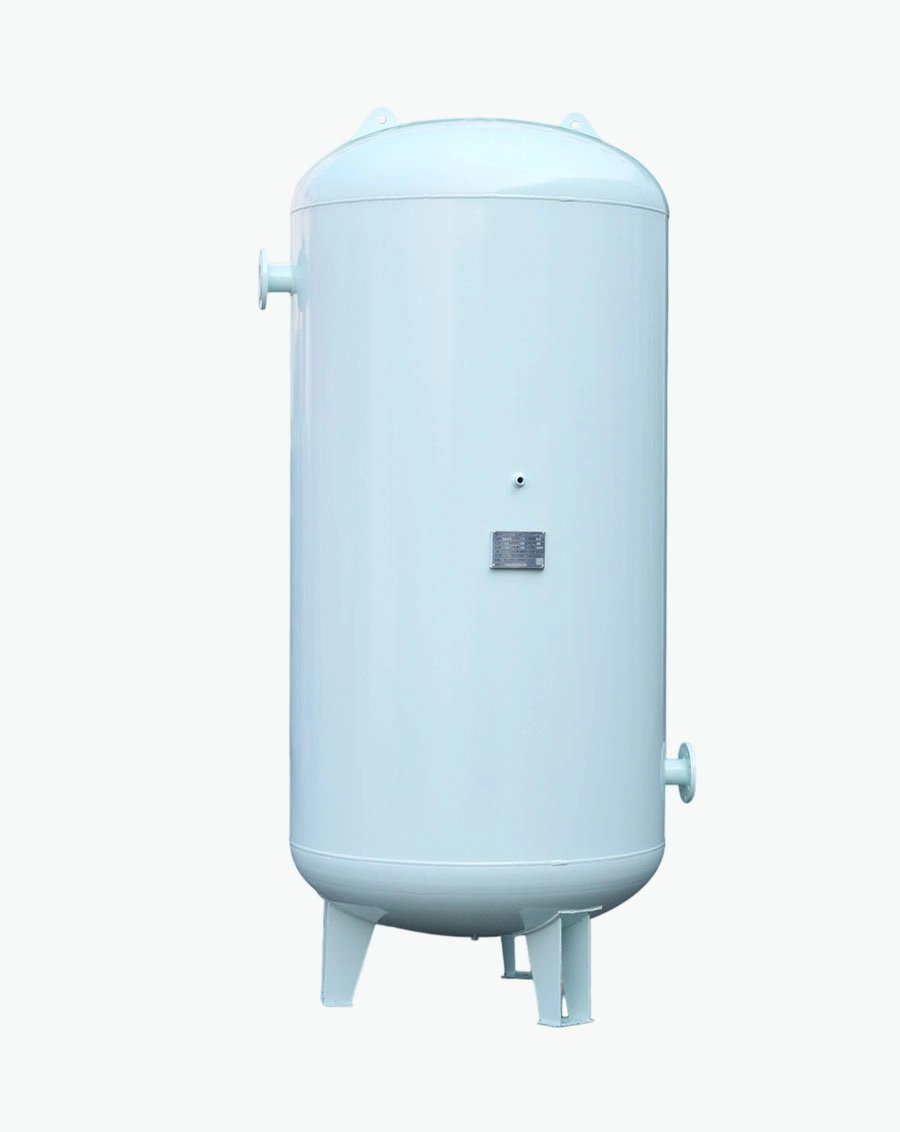
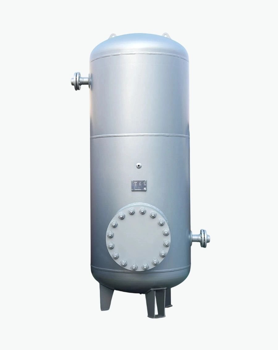
The CDU is the control point. The vessels around it — expansion, reservoir, buffer, separator, degasser — are what keep the fluid it controls in specification.
For AI infrastructure, CDU availability requirements are severe. A training run that has executed for a week cannot tolerate an unplanned cooling interruption.
Redundancy strategies:
N+1 or N+N pumps within the CDU — hot‑swappable where the design allows
N+1 CDUs at row or hall level — one spare unit serving a group of racks, with automatic or manual changeover
Diversified CDU sizing — several mid‑size units rather than one large unit, so a single failure removes a smaller fraction of capacity
Dual power feeds to CDU controls and pumps
Buffer capacity on the facility side to bridge the changeover interval
Serviceability features to specify: hot‑swappable pumps, front‑access filters with isolation valves, removable sensor assemblies, drain and sample points, and a control system that supports online firmware updates and configuration backup.
Availability claims in vendor literature should be examined for their basis. Some manufacturers cite very high availability figures; what matters for your project is the failure mode analysis — what happens on each single fault, how long recovery takes, and whether cooling is maintained during recovery.
Do I need a CDU for every rack?No. Deployment models include in‑rack CDUs (one per rack or per few racks), in‑row CDUs serving a row, and sidecar units adjacent to a rack. Larger L2L units at 1‑2 MW can serve on the order of seven to a dozen high‑density racks. The choice depends on rack density, redundancy strategy, floor space and service philosophy.
What is the difference between a CDU and a chiller?A chiller makes cold by mechanical refrigeration. A CDU distributes and controls cold that already exists in the facility water. The CDU has no compressor. Some L2A CDUs include a refrigeration circuit, but the mainstream L2L CDU is a heat exchanger and pump set with controls.
What approach temperature should I specify?As low as the budget allows — 2‑3 K is the high‑performance range, 3‑5 K is typical. Every kelvin of approach is permanently added to your facility water temperature requirement and reduces free‑cooling hours.
What flow rate per rack should I plan for?Around 1.5 L/min per kW at a 10 K secondary ΔT, giving roughly 170‑195 L/min for a 120‑130 kW rack. Add 15‑20 % headroom for CDU selection. Confirm against the specific rack OEM's published requirement.
Can the facility water be at a different pressure than the secondary loop?Yes — that is the point. The heat exchanger isolates them hydraulically. Facility water commonly runs at several bar; secondary‑side components are typically rated in the 2.4‑3.5 bar range. The CDU's secondary‑side pressure control keeps the rack loop within its rating.
How do I prevent condensation on cold plates?Keep secondary supply temperature above the white‑space dew point. This is a control function, not a passive one — the CDU controller must have a dew point input or a supply temperature floor that respects it. This is one reason cold supply temperatures (W17 class) are harder to manage in humid climates and why the industry is moving toward warmer classes.
What coolant goes in the secondary side?Typically PG25 — 25 % propylene glycol with treated water and an OAT, silicate‑free inhibitor package — per the IT equipment vendor's specification. See What Coolants Are Used in AI Data Center Liquid Cooling?
Do CDUs need expansion vessels and air separation?Most integrate a reservoir and expansion volume on the secondary side. Whether you need external vessels depends on total secondary loop volume versus the CDU's stated maximum supported external volume. Air and dirt separation is normally specified separately, on the return side.
What communications protocol should I require?Modbus TCP and SNMP are widely supported; Redfish is increasingly expected for integration with modern DCIM and for out‑of‑band management. Specify what your DCIM actually supports, and require the vendor to demonstrate the integration.
A CDU datasheet lists capacity, approach, flow and footprint. It does not tell you whether the secondary loop volume exceeds the unit's supported envelope, whether the precharge and fill pressures are correct for your static head, whether your facility water quality is compatible, or whether the reservoir volume gives adequate air release dwell time.
Send us your CDU model, rack count and heat load, secondary loop volume, coolant specification, static height and facility water conditions, and we will specify and supply the matched expansion vessel, coolant reservoir, buffer tank, air/dirt separator and deaeration equipment — with the supporting calculations and material certifications.

Specializing in pressure vessel manufacturing, we provide reliable, certified, and customized solutions for customers across diverse industries worldwide.
No.268 Xinda Road, High-tech Industrial Park, Longkou City,Shandong Province
Copyright © 2026 Yantai Xinglong Pressure Vessel Manufacturing Co., Ltd All Rights Reserved.




 عربي
عربي
 Español
 Русский
