
Stay updated with the latest company news, product innovations, exhibition highlights, and industry trends. Explore valuable insights into pressure vessel technologies and global markets.
Standard off-the-shelf air receiver tanks satisfy many general industrial applications, but specialized operating conditions, space constraints, regulatory requirements, and performance objectives frequently demand custom-engineered solutions. Custom air receiver tank design involves balancing competing priorities including pressure ratings, volume capacity, material selection, spatial footprint, connection configurations, mounting arrangements, and compliance with applicable codes and standards.
For manufacturers serving diverse international markets, mastering custom design capabilities differentiates offerings from commodity competitors while enabling premium pricing for engineered solutions addressing unique customer challenges. Successful custom designs require deep understanding of thermodynamic principles, structural mechanics, fluid dynamics, manufacturing processes, and application-specific operational requirements.
This comprehensive guide examines critical engineering considerations governing custom air receiver tank design, providing decision frameworks for optimizing specifications against application needs. By understanding the interplay between design parameters, manufacturing constraints, and operational performance, engineers and procurement specialists can collaborate effectively to develop custom solutions delivering superior value compared to standard alternatives.
Custom design begins with precise definition of operating conditions exceeding standard catalog offerings. Maximum allowable working pressure (MAWP) determines wall thickness requirements according to pressure vessel code formulas:
t = (P × R) / (S × E - 0.6 × P) + Corrosion Allowance
Where t is required thickness, P is design pressure, R is inside radius, S is allowable stress, E is joint efficiency, and corrosion allowance accounts for material loss over design life.
Design temperature affects material selection and allowable stress values. Elevated temperatures (>100°C) reduce material strength requiring thicker walls or higher-grade alloys. Low temperatures (<-20°C) risk brittle fracture in carbon steels necessitating impact-tested materials or stainless steel alternatives. Thermal cycling applications demand fatigue-resistant designs accommodating
expansion/contraction stresses.
Pressure fluctuation patterns influence fatigue life calculations. Systems experiencing frequent pressure cycling (>1000 cycles/year) require detailed fatigue analysis per ASME Section VIII Division 2 or EN 13445 methodologies. Smooth internal surfaces, generous radii at geometric transitions, and avoidance of stress concentrators extend fatigue life significantly.
Required storage volume depends on system dynamics including compressor capacity, demand patterns, acceptable pressure drop, and control strategy. Detailed calculations consider:
Demand Profile Analysis: Historical flow data reveals peak demands, average consumption, and duty cycles. Systems with high peak-to-average ratios (>3:1) benefit from larger receivers absorbing transient spikes without requiring oversized compressors.
Compressor Response Characteristics: Start-up time, load acceptance rate, and minimum run times determine how quickly compressors respond to pressure changes. Slow-responding units (reciprocating compressors, large centrifugals) need larger buffers than fast-modulating screw compressors with variable speed drives.
Acceptable Pressure Band: Wider pressure swings allow longer compressor off-times improving efficiency but may exceed application tolerances. Narrow bands require larger receivers maintaining stability during compressor transitions. Critical processes may need dedicated receivers with local regulators isolating them from main system variations.
Future Expansion Planning: Anticipating production growth prevents premature obsolescence. Modular designs allowing additional receiver banks provide flexibility without complete system replacement. However, over-sizing wastes capital and floor space requiring careful forecasting balanced against adaptability.
Rule-of-thumb sizing provides initial estimates requiring refinement through dynamic simulation:
● General industrial: 7-10 liters per m³/min compressor capacity
● Intermittent high-demand: 15-25 liters per m³/min
● Critical process with tight pressure control: 20-40 liters per m³/min
● VSD compressor systems: 10-20 liters per m³/min (smaller than fixed-speed due to modulation capability)
Nozzle locations, sizes, and orientations significantly impact installation feasibility, maintenance access, and system performance. Custom designs optimize connection layouts considering:
Inlet Connections: Sized matching compressor discharge piping diameter minimizing pressure drop. Multiple inlet nozzles enable parallel compressor feeds or future expansion. Inlet diffusers or baffles reduce velocity promoting condensate separation.
Outlet Connections: Positioned above expected condensate level preventing liquid carryover.
Multiple outlets serve different pressure zones or redundancy requirements. Outlet nozzles often larger than inlets accommodating distribution system flows exceeding single compressor capacity.
Drain Connections: Located at lowest point ensuring complete condensate removal. Automatic drain valves require adequate clearance for maintenance and replacement. Manual drain valves serve as backups or for facilities preferring manual control. Drain line sizing prevents restriction during rapid discharge.
Instrumentation Ports: Pressure gauge connections, temperature sensors, level indicators, and safety valve mounts require threaded or flanged openings positioned for visibility and accessibility. Redundant instrument ports facilitate calibration without system shutdown.
Safety Relief Valve Mounting: Direct vertical mounting preferred minimizing backpressure effects on valve performance. Discharge piping routes safely away from personnel areas complying with noise and velocity regulations. Some jurisdictions require specific relief valve capacities based on compressor input power rather than receiver volume.
Vertical orientation maximizes footprint efficiency and enhances gravity-driven condensate drainage. Horizontal configurations suit low-ceiling installations or when length-wise space availability exceeds height clearance. Elliptical or spherical shapes offer alternative geometries for extreme space constraints though complicating fabrication increasing costs.
Balancing structural integrity against weight and cost requires iterative thickness optimization considering:
Code Compliance: ASME Section VIII, EN 13445, GB 150, and other applicable standards prescribe minimum thicknesses based on pressure, diameter, material properties, and joint efficiency factors. These form baseline requirements subject to increase for practical considerations.
Corrosion Allowance: Additional thickness compensates for anticipated material loss over design life. Typical allowances range 1-3mm for carbon steel in moderate environments, 0.5-1mm for stainless steel, and 0mm for composite materials. Aggressive environments (chemical exposure, coastal salt spray, high humidity) warrant increased allowances or enhanced protection systems.
Manufacturing Tolerances: Plate thickness variations, forming distortions, and weld shrinkage require nominal thickness exceeding calculated minimums ensuring all locations meet code requirements after fabrication. Standard practice adds 10-15% margin above theoretical minimums.
Handling and Transportation Stresses: Thin-walled large-diameter vessels risk denting or ovalization during lifting, shipping, and installation. Temporary stiffening rings, careful rigging procedures, and conservative thickness selections prevent damage compromising long-term integrity.
Finite element analysis (FEA) enables detailed stress mapping identifying localized high-stress areas requiring reinforcement. Nozzle reinforcements, support skirt attachments, and lifting lug connections benefit from FEA verification ensuring adequate margins beyond simplified code calculations.
Receiver tanks require robust support systems transferring weight to foundations while accommodating thermal expansion and seismic loads where applicable. Support design considerations include:
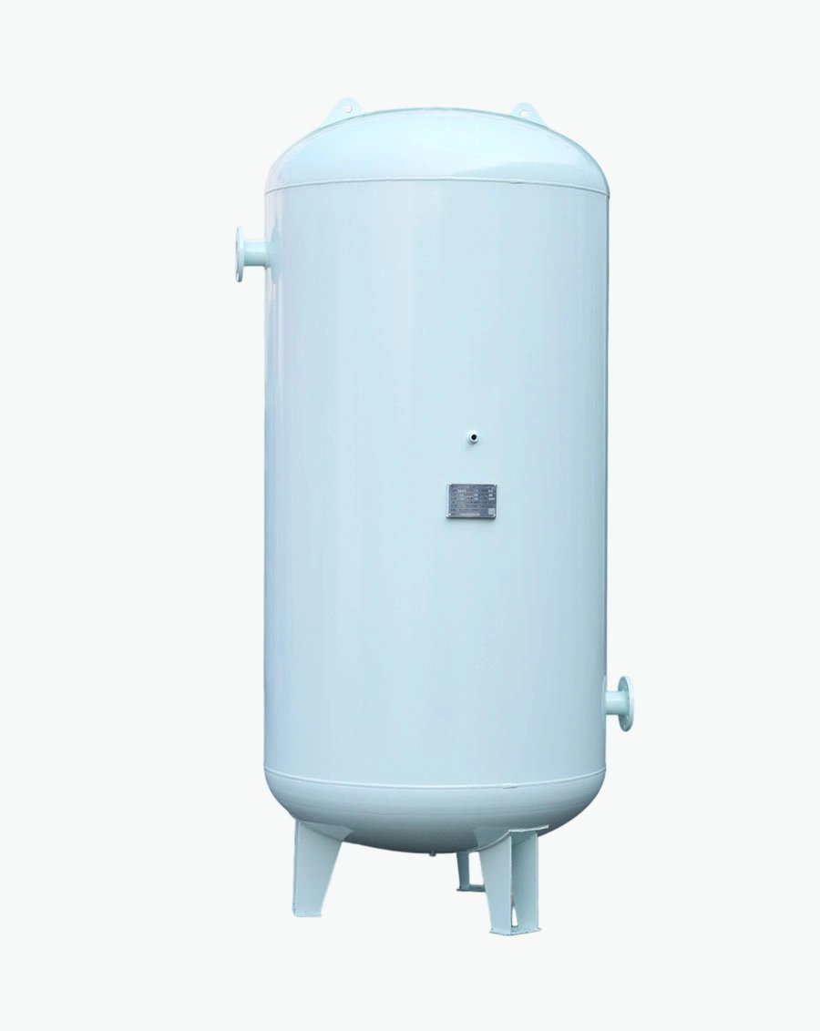
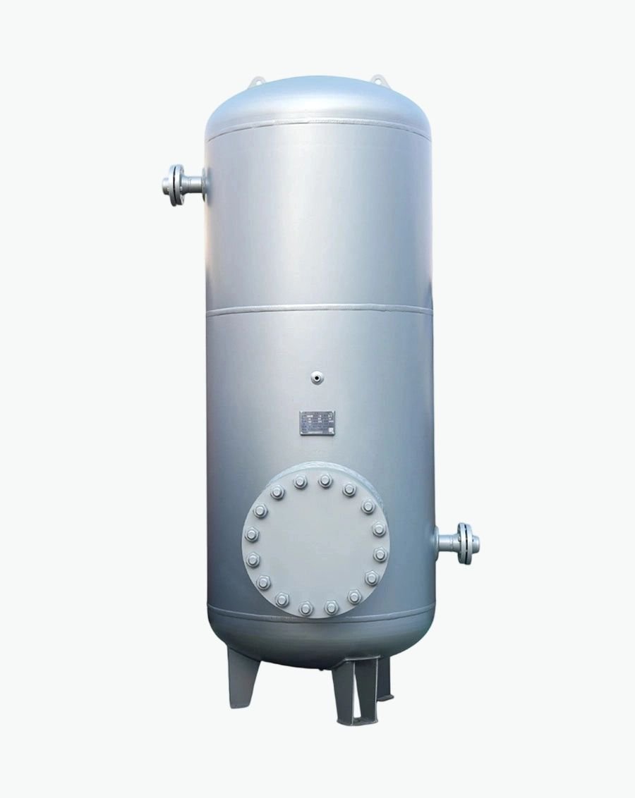
Leg Supports: Most common for vertical tanks, typically three or four legs spaced symmetrically. Leg sizing accounts for vertical weight, overturning moments from wind or seismic forces, and eccentric loading from asymmetric nozzle arrangements. Base plates distribute loads to concrete foundations preventing punching failures.
Skirt Supports: Cylindrical skirts wrapping tank bottoms provide continuous support distributing loads uniformly. Skirts simplify foundation design but complicate underside inspection and coating maintenance. Drainage gaps prevent water accumulation causing hidden corrosion.
Saddle Supports: Horizontal tanks rest on saddle supports conforming to shell curvature. Two saddles minimum prevent excessive bending; additional saddles reduce span lengths for very long vessels. Saddle angles typically 120-150 degrees balancing support area against thermal expansion restraint.
Thermal Expansion Accommodation: Fixed supports at one end combined with sliding or guided supports at opposite ends allow axial expansion without inducing excessive thermal stresses.
Expansion joints in connecting piping complement tank movement preventing nozzle overload.
Seismic Design: Earthquake-prone regions require seismic analysis per local building codes considering horizontal and vertical acceleration components. Bracing systems, anchor bolt capacities, and foundation designs must resist seismic forces while maintaining functionality post-event. Dynamic analysis models tank-fluid interaction effects amplifying seismic responses.
While carbon steel and stainless steel dominate standard offerings, custom applications may warrant specialized materials:
High-Strength Low-Alloy Steels: ASTM A517, A514 grades provide yield strengths 690-895 MPa enabling thinner walls reducing weight. Welding requires preheat and controlled heat input preventing hydrogen cracking. Cost premiums of 20-40% over standard carbon steel justify weight-sensitive applications.
Duplex Stainless Steels: Type 2205 offers yield strength 450 MPa (double austenitic grades) with excellent chloride resistance. Ideal for offshore, chemical processing, and marine environments combining strength and corrosion resistance. Higher material costs offset by reduced thickness and extended service life.
Nickel Alloys: Inconel, Hastelloy, Monel serve extremely corrosive environments handling acidic condensate, chemical contamination, or high-temperature service. Prohibitive costs limit use to critical applications where failure consequences justify investment.
Clad Materials: Carbon steel backs clad with thin stainless or nickel alloy layers provide corrosion resistance at fraction of solid alloy cost. Explosion bonding or roll bonding creates metallurgical bonds between layers. Welding requires specialized procedures maintaining cladding integrity at joints.
Material selection impacts not only vessel itself but also attached components (nozzles, flanges, supports) requiring compatible materials preventing galvanic corrosion. Dissimilar metal joints need isolation gaskets, insulating coatings, or sacrificial anodes mitigating electrochemical degradation.
Custom designs must align with manufacturer capabilities ensuring producibility within budget and schedule constraints:
Welded Construction: Dominant method for custom receivers offering design flexibility across sizes and geometries. Longitudinal seams join rolled plates forming cylindrical shells; circumferential seams attach heads. Automated submerged arc welding increases productivity for thick sections; manual GTAW provides precision for thin stainless or exotic alloys.
Forged Components: Nozzles, flanges, and heads may utilize forged blanks rather than plate fabrication improving material properties through grain structure refinement. Forgings eliminate welds at critical locations reducing inspection requirements and potential defect sites. Cost-effective for high-volume custom programs sharing common components.
Spin Forming: Rotational forming produces seamless hemispherical or elliptical heads without welds improving structural efficiency. Limited to axisymmetric shapes and moderate thicknesses. Excellent for high -pressure small-diameter vessels where weld elimination justifies tooling investment.
Additive Manufacturing: Emerging technology enabling complex internal features (baffles, heat exchange surfaces, integrated instrumentation) impossible through conventional methods. Currently limited to small volumes and exotic materials due to high costs and size constraints. Future potential for highly customized specialty receivers.
Quality assurance protocols vary by fabrication method requiring alignment with applicable code requirements. Welded construction demands extensive NDE (radiography, ultrasonics, dye penetrant) verifying joint integrity. Forged components require material certification and dimensional inspection. Additive parts need layer-by-layer monitoring and post-build heat treatment validation.
Custom surface finishes address specific environmental and hygiene requirements:
Internal Coatings: Epoxy phenolic linings resist condensate corrosion extending carbon steel service life. Food-grade epoxy formulations meet FDA requirements for incidental contact applications. Application requires thorough surface preparation (Sa 2.5 blast profile), controlled humidity/temperature during curing, and holiday detection testing verifying coating continuity.
External Coatings: Multi-coat systems combine zinc-rich primers (cathodic protection), epoxy intermediates (barrier protection), and polyurethane topcoats (UV resistance, aesthetics). Color coding identifies system contents per industry conventions (blue for compressed air). Thickness specifications typically 200-300 microns total dry film thickness.
Stainless Steel Finishes: Mechanical polishing achieves Ra < 0.8 μm for hygienic applications facilitating cleaning and preventing bacterial adhesion. Electropolishing enhances passive film quality providing superior corrosion resistance and cleanability. Passivation treatments (nitric or citric acid) remove free iron contamination restoring uniform corrosion resistance.
Specialty Coatings: Fluoropolymer coatings (PTFE, PVDF) resist aggressive chemicals and provide non-stick surfaces preventing contaminant buildup. Ceramic coatings withstand extreme temperatures and abrasion for harsh environments. Rubber linings dampen vibration and provide chemical resistance for specific applications.
Coating specification should reference recognized standards (SSPC, NACE, ISO 12944) defining surface preparation, application methods, inspection criteria, and performance expectations.
Third-party coating inspectors verify compliance ensuring long-term protection effectiveness.
Custom designs targeting international markets must satisfy multiple regulatory frameworks simultaneously:
ASME BPVC Section VIII: Requires authorized inspector involvement throughout fabrication, material traceability documentation, weld procedure qualifications, and U-stamp certification. Design calculations sealed by professional engineer registered in applicable jurisdiction. Nameplate includes MAWP, design temperature, serial number, and year built.
European PED 2014/68/EU: Categorizes vessels by pressure-volume product determining conformity assessment route. Category III-IV vessels need notified body design examination and production quality audits. Technical files maintain design calculations, material certificates, inspection reports, and EU Declaration of Conformity. CE marking mandatory for market access.
Chinese GB Standards: GB 150 governs design while TSG 21 establishes administrative requirements including special equipment manufacturing licenses. Imported vessels require Chinese inspection agency verification and translated documentation. Local representation facilitates regulatory communications and periodic inspection coordination.
Other Regional Codes: Japanese JIS B 8243, Korean KSB B6211, Australian AS 1200, Indian IS codes each present unique requirements. Harmonization efforts through ISO standards simplify multi-market compliance but national amendments persist requiring careful attention to destination-specific rules.
Platform design strategies identify common denominators across target codes establishing baseline specifications meeting most stringent requirements. Variable elements (nameplates, documentation formats, optional features) customize per destination avoiding complete redesigns for each market.
Custom projects generate extensive documentation supporting certification and future reference:
Design Package: Calculation sheets showing code compliance, FEA reports for complex geometries, material specifications with mill certificates, welding procedure specifications (WPS), and procedure qualification records (PQR). Drawings include general arrangements, detail drawings for nozzles and supports, and weld maps identifying joint locations and NDE requirements.
Manufacturing Records: Material traceability logs linking plates and components to mill test reports, welder qualification certificates, NDE reports with examiner certifications, heat treatment records if applicable, hydrostatic test charts documenting test pressure and hold times, and dimensional inspection reports verifying conformance to drawings.
Certification Documents: ASME Data Reports signed by authorized inspectors, EU Declarations of Conformity with notified body numbers, Chinese special equipment registration certificates, and any additional customer-specific documentation requirements. Translations into local languages where mandated.
Operation and Maintenance Manuals: Installation instructions, commissioning procedures, operating limitations, maintenance schedules, spare parts lists, and troubleshooting guides.
Multilingual versions support international installations. Digital formats enable easy updates and remote access.
Documentation management systems organize these materials ensuring retrievability throughout vessel lifecycle. Cloud-based platforms facilitate sharing among stakeholders while maintaining version control and access permissions. Retention periods vary by jurisdiction (typically 10-30 years) requiring long-term archival strategies.
High-Pressure Specialty Gas Application
A semiconductor manufacturer required 500-liter receivers rated for 30 bar (435 psi) handling ultra-high purity nitrogen with strict contamination controls. Standard 13 bar receivers proved inadequate necessitating custom engineering.
Design solutions included:
● ASTM A516 Grade 70 carbon steel with 16mm wall thickness (vs. 8mm for standard 13 bar)
● Internal electropolished stainless steel liner preventing particle generation
● Orbital-welded sanitary fittings eliminating crevices trapping contaminants
● Helium leak testing verifying <1×10^-9 mbar·L/s leakage rates
● Cleanroom assembly and packaging preventing particulate contamination
Results achieved:
● Met SEMI F21 purity standards enabling direct tool integration
● Eliminated downstream filtration reducing pressure drop and maintenance
● Extended service intervals from annual to triennial inspections
● Premium pricing justified by performance differentiation
A downtown commercial building needed 2000-liter compressed air storage for HVAC controls but faced severe height restrictions (2.5m ceiling) and limited floor space. Standard vertical tanks exceeded available clearance.
Custom approach delivered:
● Horizontal elliptical design (3.5m length × 1.2m width × 1.8m height) fitting within constraints
● Integrated sound attenuation lining reducing compressor noise transmission to occupied spaces
● Decorative exterior paneling matching building aesthetics satisfying architectural requirements
● Remote-mounted instrumentation enabling monitoring without accessing confined installation space
● Modular construction allowing delivery through standard doorways and assembly on-site
Outcomes realized:
● Solved spatial challenge without relocating mechanical equipment to expensive rooftop
● Noise reduction eliminated tenant complaints enabling lease renewals
● Aesthetic integration preserved building design intent maintaining property values
● Demonstrated custom design value beyond technical specifications
Custom air receiver tank design transforms standard pressure vessels into optimized solutions addressing unique application challenges through careful engineering of operating parameters, structural configurations, material selections, and manufacturing processes. Success requires balancing technical performance against economic viability while navigating complex regulatory landscapes across global markets.
Manufacturers investing in custom design capabilities differentiate their offerings from commodity suppliers commanding premium pricing for engineered value. Collaboration between customers providing detailed application knowledge and manufacturers contributing technical expertise produces optimal outcomes exceeding what either party could achieve independently.
Future trends including digital twin simulations, additive manufacturing integration, and smart sensor incorporation promise even greater customization possibilities. However, fundamental engineering principles governing pressure containment, structural integrity, and operational reliability remain timeless foundations upon which innovative custom solutions build sustainable competitive advantages in evolving industrial markets.
By mastering the considerations outlined in this guide, engineering teams develop custom air receiver specifications delivering superior performance, longevity, and total cost of ownership compared to standard alternatives while satisfying the most demanding application requirements across diverse industrial sectors.

Specializing in pressure vessel manufacturing, we provide reliable, certified, and customized solutions for customers across diverse industries worldwide.
No.268 Xinda Road, High-tech Industrial Park, Longkou City,Shandong Province
Copyright © 2026 Yantai Xinglong Pressure Vessel Manufacturing Co., Ltd All Rights Reserved.




 عربي
عربي
 Español
 Русский
