
Stay updated with the latest company news, product innovations, exhibition highlights, and industry trends. Explore valuable insights into pressure vessel technologies and global markets.
Thermal ride‑through, hydraulic decoupling and the component that keeps GPU racks online during a chiller restart
A buffer tank is a large vessel of stored chilled water or coolant whose purpose is stored thermal capacity — it buys time and stabilizes the loop.
It does three jobs: thermal ride‑through during chiller failure or restart, hydraulic decoupling of the primary (chiller plant) and secondary (IT load) circuits, and damping of temperature swings from bursty AI workloads.
Core sizing equation: \(V=Q ×t /(\rho ×c_{p} ×\Delta T)\). For water this reduces to \(V(m^{3})=Q\ (kW) ×t(h) /(1.163 ×\Delta T(K))\).
Worked example: 500 kW of IT load, 3 minutes of ride‑through, 5 K allowable temperature rise → ≈4,300 L, or ≈5,160 L with a 1.2 safety factor.
Rules of thumb in the market: 4 L per kW of chiller capacity for comfort cooling, up to 11 L per kW for process and multifunction chillers; ASHRAE‑referenced practice commonly uses 5 minutes of storage at design flow.
Ride‑through targets in data center practice span roughly 30 seconds to 15 minutes, set by how fast standby generation and chiller restart complete — not by an arbitrary number.
Typical capacity: 500–10,000 L at rack or row scale, 10,000–100,000 L and beyond for hall‑scale chilled water thermal energy storage.
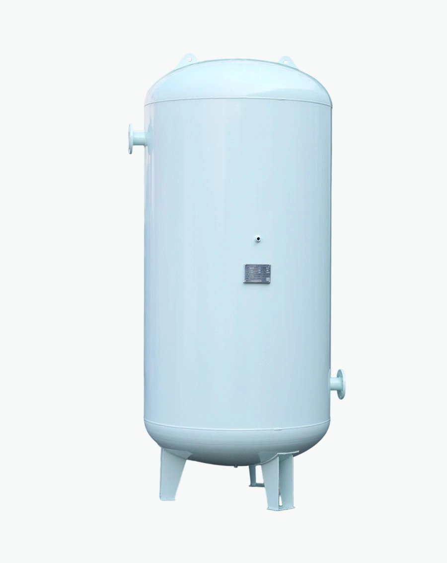
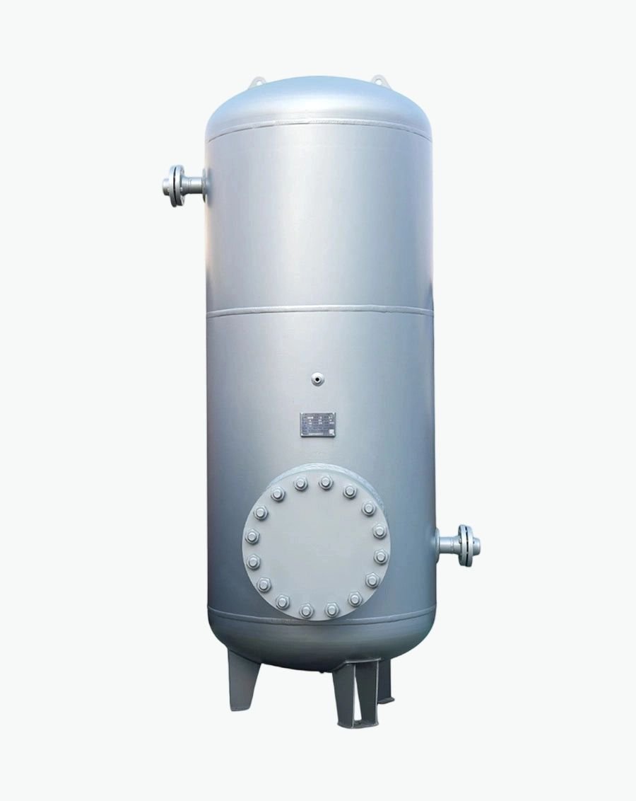
A buffer tank — also called a thermal storage tank, chilled water storage tank, accumulation tank or decoupling tank — is a large, insulated vessel of water installed in a cooling circuit to add thermal mass. Unlike an expansion vessel, it contains no gas cushion and no membrane; it is simply liquid‑full (or near‑full), open to a vent or fitted with a breather, and connected into the circuit so that stored cold fluid can be drawn on demand.
The engineering logic is straightforward. Cooling plant fails, restarts or ramps far more slowly than an IT load can tolerate. A GPU rack running a training job dissipating 120 kW or more cannot wait for a chiller compressor to come back online — coolant temperatures
\(V = N × 60 × Z /(4.18 × \Delta T)\)
\(V=(Q × t) /(\rho × c_p × \Delta T)\)
\(V=Q × t /(1.163 × \Delta T)\)
\(V(L)=Q(kW) × t(s) /(4.187 × \Delta T(K))\)
Coolant specific heat kJ/(kg∙K)
water: (ρ ≈ 1 000 kg/m³, \(c_p\) ≈ 4.18 kJ/kg∙K), with V in m³, Q in kW, t in hours and ΔT
| Buffer tank | Expansion vessel | Coolant reservoir | |
| Manages | Thermal energy | Pressure | Fluid inventory |
| Size class | 10³‑10⁵ L | 10¹‑10³ L | 10¹‑10² L |
| Gas cushion | No | Yes, pre‑charged | No (passive headspace) |
| Membrane | No | Yes | No |
| Insulated | Yes, heavily | Usually no | Sometimes |
| If omitted | No ride‑through; chiller short‑cycling; flow coupling | Overpressure, relief discharge, air ingress, cavitation | No make‑up, no deaeration, no level visibility |
enables chillers to run at night or during low‑tariff periods. Raising chilled water supply temperature even 1 °C saves on the order of 4 % of cooling energy, and a buffer tank makes higher supply temperatures tolerable by smoothing transients.
Depends on which risk you are mitigating. Plant‑level failures (chiller trip, generator transfer) are mitigated on the primary/FWS side. Load‑side transients and CDU‑level response are mitigated on the secondary/TWS side. Large deployments often have both.
Facility side: carbon steel with internal coating, or stainless where budget allows.
Technology side: 316L stainless is the default recommendation, because the loop is clean, filtered to 25 µm or finer, and any corrosion product will be carried into cold plates. See our materials guide Liquid Cooling Reservoir Materials: 304 vs 316L Stainless Steel.
Yes. Use the actual ρ and \(c_p\) of the coolant. PG25 has roughly 5–10 % lower volumetric heat capacity than water, so a glycol loop needs a proportionally larger tank for the same ride‑through.
A buffer tank is a large, expensive, structurally significant item that is very hard to change after the slab is poured. The inputs that determine its size are few and knowable: heat load, ride‑through time, allowable ΔT, coolant properties, and location in the circuit. Send us those five inputs and we will return a calculated volume, a tank specification (material, insulation, nozzles, instrumentation), and the supporting calculation sheet you can put in front of a consulting engineer.

Specializing in pressure vessel manufacturing, we provide reliable, certified, and customized solutions for customers across diverse industries worldwide.
No.268 Xinda Road, High-tech Industrial Park, Longkou City,Shandong Province
Copyright © 2026 Yantai Xinglong Pressure Vessel Manufacturing Co., Ltd All Rights Reserved.




 عربي
عربي
 Español
 Русский
